
By an industry veteran in custom machine vision systems and industrial hardware integration.
Key Takeaways
- Shutter Speed vs. Conveyor Speed: Eliminating Motion Blur
- Lighting Geometry: Designing the Perfect Visual Highlight
- Lens Selection and Working Distance: Protecting the Field of View
- Calibration: Teaching the System Scale and Perspective
- The AdaptNXT Machine Vision Checklist
Imagine this scenario, which plays out in dozens of manufacturing facilities every month:
An engineering team trains a deep learning model to inspect metal parts for defects. Using a dataset of high-resolution images shot in a clean laboratory environment, the model achieves an outstanding 99.5% accuracy rate. The project is approved, the budget is unlocked, and the team deploys the model to the production floor.
Need an Expert Opinion?
Stop guessing. Speak directly with a senior AdaptNXT engineer about your architecture, timeline, and feasibility.
Within 48 hours, the system is a disaster. It is flagging normal parts as defective (false positives), missing actual cracks (false negatives), and struggling to keep up with the line speed. The operators are frustrated, management is skeptical, and the project is put on hold.
What went wrong?
The code didn't break. The neural network architecture was fine. The failure occurred because the team treated computer vision as a pure software challenge, ignoring the laws of physics. In the lab, the lighting was consistent, the parts were static, and the camera was clean. On the shop floor, the parts are moving at 2 meters per second, the ambient daylight shifts throughout the day, vibrations shake the camera mount, and dust coats the lens.
In industrial computer vision, the algorithm is only 20% of the battle. The other 80% is physical installation: camera selection, lens design, lighting geometry, calibration, and environmental protection. If you don't get the physical image acquisition right, your state-of-the-art AI is essentially analyzing static noise.
At AdaptNXT, we specialize in shipping computer vision models that actually work in production. This guide details the critical physical design principles you must implement to ensure your computer vision system performs as well on the shop floor as it did in the lab.
Shutter Speed vs. Conveyor Speed: Eliminating Motion Blur
The first physical constraint you must address is motion. On an automated assembly line, parts are moving. If your camera's shutter speed is too slow, the movement of the part during the exposure window will smear the pixels, creating motion blur. While the human eye can tolerate slight blur, a neural network trained on sharp features will fail to identify defects.
To eliminate motion blur, you must calculate your maximum allowable exposure time based on your line speed and your target defect size. Here is the standard calculation formula:
\[ ext{Exposure Time (Seconds)} \le rac{ ext{Pixel Resolution (mm/pixel)} imes ext{Acceptable Blur (Pixels)}}{ ext{Conveyor Velocity (mm/second)}}\]
A Practical Example
Suppose you are inspecting automotive stampings on a conveyor belt moving at 1.5 meters per second (1,500 mm/s). You are using a 5-megapixel camera with a field of view that yields a pixel resolution of 0.1 mm per pixel. To detect microscopic cracks, you cannot tolerate more than 1 pixel of motion blur.
Using the formula:
\[ ext{Exposure Time} \le rac{0.1 ext{ mm} imes 1 ext{ pixel}}{1500 ext{ mm/s}} = 0.000067 ext{ seconds} \approx 67 ext{ microseconds}\]To run a shutter speed of 67 microseconds (1/15,000th of a second), your camera sensor will receive very little light. If you rely on standard ambient warehouse lighting, your image will be completely black. This brings us to the next critical component: dedicated industrial lighting.
Lighting Geometry: Designing the Perfect Visual Highlight
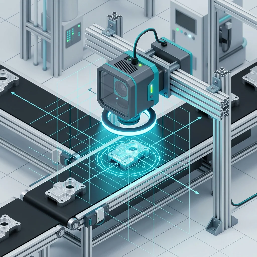
Standard overhead fluorescent lighting is the enemy of machine vision. It varies with the time of day, creates harsh shadows, and flickers at 50/60 Hz (which creates bands of dark and light at high shutter speeds). To get consistent results, you must shroud the inspection area to block ambient light and deploy structured, high-intensity industrial LED illumination.
The type of light you use depends entirely on the physical characteristics of the part and the defect you are looking for. We use four main lighting geometries:
Lighting Type How It Works Best For Ring Light Bright, direct light mounted around the camera lens, projecting light straight down. Creating high contrast on matte surfaces, highlighting printed text or labels. Avoid on reflective metal. Dome Light (Cloudy Day) LEDs project light upward into a reflective dome, creating soft, diffuse, omnidirectional illumination. Highly reflective, curved, or metallic parts. Eliminates specular glare and hot spots on metal/plastic. Backlighting A light panel is placed physically behind the part, projecting light straight into the camera lens. Creating a sharp, black silhouette. Perfect for dimension verification, thread checking, and hole alignment. Low-Angle Bar Light (Darkfield) Light is projected at a very shallow angle (10-15 degrees) relative to the part surface. Surface defects like scratches, dust, or dents on polished surfaces. The flat surface remains dark, while scratches catch the light and glow. For high-speed lines, we often run strobe lighting controllers. By pulsing the LEDs at high intensity for only a few microseconds synchronously with the camera shutter, we generate brilliant, blur-free images without heat buildup or premature LED degradation.
Lens Selection and Working Distance: Protecting the Field of View
A camera sensor is only as good as the glass in front of it. Choosing a lens is not just about matching the mount; it requires calculating the correct focal length to cover your target Field of View (FOV) at a specific Working Distance (WD).
The relationship is defined by the basic lens formula:
\[ ext{Focal Length (mm)} = rac{ ext{Working Distance (mm)} imes ext{Sensor Size (mm)}}{ ext{Field of View (mm)}}\]If you choose a lens with too short a focal length (a wide-angle lens) to fit a tight space, you will introduce barrel distortion — the image will bulge in the center, skewing your measurements and confusing your AI models. To ensure dimensional accuracy across the entire image, we often specify telecentric lenses. These specialized lenses eliminate perspective distortion entirely, ensuring an object appears the same size regardless of its distance from the camera.
Additionally, on a factory floor, you must protect the lens. Airborne oil mist, dust, water spray, and mechanical vibrations will quickly ruin exposed optics. We deploy custom machine vision enclosures equipped with optical-grade protective windows (often quartz or sapphire glass), air knives to blow away dust, and vibration-dampening mounts.
Calibration: Teaching the System Scale and Perspective
When your camera captures an image, it records it in pixels. But your manufacturing tolerance is defined in millimeters. To bridge this gap, your computer vision system must undergo geometric calibration.
We do this by capturing images of a highly precise checkerboard or dot grid target placed at the exact working distance of the part. Because we know the physical distance between the checkerboard squares (e.g., exactly 10.00 mm), we can calculate the pixel-to-millimeter ratio.
More importantly, calibration allows us to calculate the Camera Matrix, which maps the 3D space of the physical shop floor to the 2D coordinate system of the sensor, automatically correcting for:
- Lens radial and tangential distortion
- Perspective distortion caused by the camera being mounted at a slight angle relative to the conveyor
- Conveyor belt vibration and wobble
Without calibration, your computer vision measurements will drift every time the temperature in the warehouse changes or a technician slightly nudges the camera during maintenance.
The AdaptNXT Machine Vision Checklist
When we design custom computer vision solutions for our clients — such as our deployments in railway wagon inspection and driver drowsiness monitoring — we run every camera station through this physical validation process before training the AI:
- Line Speed Calculation: Is the shutter speed calculated to limit motion blur to less than 1 pixel?
- Ambient Shrouding: Is the inspection area enclosed to completely eliminate fluctuating warehouse light?
- Lighting Geometry Validation: Does the lighting type highlight the target defect (e.g., low-angle bar for scratches on metal)?
- Optical Distortion Check: Are telecentric or low-distortion lenses used for measurement tasks?
- Environmental Enclosure: Is the camera protected against dust, humidity, oil, and vibration?
- Automated Calibration Routine: Is there a software routine to re-calibrate pixel-to-mm conversions after maintenance?
The Bottom Line
Deep learning models are incredibly powerful, but they cannot compensate for poor physical photography. A high-quality, high-contrast, properly lit, and distortion-free image makes the AI model's job simple and highly reliable. A noisy, blurry, glare-ridden image makes it impossible. (To understand how this engineering setup translates directly to plant-floor cost savings and OEE improvements, see our guide on Calculating the ROI of Computer Vision).
If you want to deploy a computer vision system that runs reliably 24/7 on your line, stop looking at software code alone. Look at the camera mount, check the lighting geometry, and test the calibration.
At AdaptNXT, we are not just software developers. We are systems engineers who understand the physics of the factory floor. We custom-design the lighting, select the lenses, and build the physical enclosures to ensure our AI models perform with 99.9% reliability in your specific operating environment. Connect with our computer vision architects to discuss your project →
Ready to streamline your operations and drive growth? Contact our team today to explore how our advanced solutions can be tailored to your business needs, or discover your potential savings with our ROI Calculator.
Summary Overview
| Concept / Strategy | Description |
|---|---|
| Shutter Speed vs. Conveyor Speed: Eliminating Motion Blur | How to calculate the maximum allowable exposure time to prevent pixel smearing on moving parts. |
| Lighting Geometry: Designing the Perfect Visual Highlight | A breakdown of different lighting setups like dome and ring lights to highlight specific defects. |
| Lens Selection and Working Distance: Protecting the Field of View | Choosing the correct focal length and lenses to ensure dimensional accuracy and avoid distortion. |
| Calibration: Teaching the System Scale and Perspective | The process of mapping physical space to pixel space for reliable measurement and analysis. |
| The AdaptNXT Machine Vision Checklist | A crucial physical validation checklist to run through before deploying your AI model. |
| The Bottom Line | The importance of prioritizing physical camera and lighting setup for reliable computer vision deployments. |
Frequently Asked Questions (FAQ)
Why do computer vision models fail on the factory floor?
They often fail because environmental factors like motion blur, inconsistent lighting, and vibrations are ignored during the physical camera setup.
What type of lighting is best for computer vision on reflective metal parts?
Dome lighting, or "cloudy day" lighting, is ideal for reflective metal as it creates soft, diffuse illumination that eliminates harsh specular glare.
Why is geometric calibration important for industrial cameras?
Calibration establishes the correct pixel-to-millimeter ratio and corrects lens distortion, ensuring that the vision system can accurately measure physical dimensions.