
As electric vehicle (EV) gigafactories scale production to hundreds of gigawatt-hours annually, cylindrical battery pack assembly lines face uncompromising quality demands. A modern EV pack integrates between 4,000 and 9,000 individual cylindrical cells—whether legacy 18650s, mainstream 21700s, or next-generation 46800 tabless form factors. At line rates processing a module every 15 to 30 seconds, a single reversed cell or missed weld alignment will cause catastrophic thermal runaway, irreversible pack scrappage, or plant-floor safety hazards during wire bonding and laser busbar welding.
Automated visual inspection powered by edge AI has shifted from an operational luxury to a mission-critical line gate. In this deep-dive technical guide, we break down the end-to-end engineering architecture required to inspect cylindrical battery modules at production line speeds: from high-specularity optical physics and darkfield/coaxial dome illumination to deep learning inference pipelines accelerated on NVIDIA Jetson with TensorRT, deterministic PLC triggering, and sub-millimeter busbar alignment.
Evaluating Automated Optical Inspection for Your Line?
Send us 5–10 sample images of your OK/NG parts or discuss your cycle-time and lighting constraints. Our Computer Vision architects will benchmark detection feasibility within 48 hours—or join a 20-min zero-pitch technical scoping session.
Key Takeaways
- Thermal Runaway Prevention: A single reversed-polarity cylindrical cell in a parallel group causes a massive direct dead short upon busbar contact, initiating thermal runaway before electrical end-of-line (EOL) testing can intervene.
- Optical Defeat of Specular Glare: Nickel-plated steel can bottoms and etched aluminum terminal caps act as mirrors; robust inspection demands diffuse coaxial telecentric illumination or multi-angle polarization lighting arrays.
- Ultra-Low Cycle Latency: Inspecting 500+ cells per module within a 2.0-second indexing window requires high-throughput INT8 TensorRT inference running locally on ruggedized edge hardware, bypassing cloud latency.
- Integrated Dual-Stage Pipelines: Combining deep learning object detection (YOLO/RT-DETR) for cell localization and polarity classification with sub-pixel morphological edge algorithms ensures sub-50 µm busbar weld center accuracy.
- Deterministic Industrial Fieldbus: Seamless industrial integration relies on GigE Vision hardware triggers combined with real-time Profinet or EtherNet/IP handshakes directly to line PLCs.
The Manufacturing Challenge: Cell Packing in Modern EV Battery Modules
The manufacturing process for cylindrical EV battery packs is an orchestration of extreme mechanical precision and electrical rigor. Whether engineering a structural battery pack (cell-to-chassis) or modular cell-to-pack architectures, the module loading station receives thousands of bare cylindrical cells from incoming sorting trays and seats them into precision plastic or composite honeycomb spacer grids.
Each cell format introduces distinct structural and inspection characteristics:
- 18650 Cells (18mm × 65mm): High cell count architectures (e.g., 7,000+ cells per vehicle pack). The tight pitch between cells creates severe shadowing at peripheral viewing angles, while the small positive terminal button requires high-resolution imaging to verify crimp ring integrity.
- 21700 Cells (21mm × 70mm): Widely adopted industry standard balancing energy density and pack packaging. The larger diameter slightly relaxes inter-cell clearance but amplifies the impact of individual cell defects on total pack thermal management.
- 46800 Cells (46mm × 80mm): Features dry-electrode coatings, structural load-bearing casings, and tabless electrode designs. The positive and negative terminal topology differs significantly from smaller cells: the center terminal button is surrounded by an active laser-welded current collector ring, demanding simultaneous concentricity inspection, polarity validation, and height profiling.
Once seated in the matrix, three critical failure modes must be eliminated before the module advances to downstream wire bonding or fiber laser welding:
- Missing Cells / Empty Pockets: Voids in the matrix skew mechanical load distribution, invalidate designed battery management system (BMS) thermal impedance models, and cause robot welding heads to blow through open air or damage bottom collector sheets.
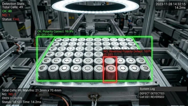
- Reversed Polarity (Anode vs. Cathode): Inserting a cell upside down places its positive cap where a negative flat bottom is expected. When the top conductive busbar plate is laser-welded across the parallel cluster, this creates a short-circuit across the entire parallel block. The resultant discharge current easily exceeds 1,000 amperes, triggering immediate thermal runaway, toxic outgassing, and localized fire on the manufacturing line.
- Cell Tilt, Seating Depth, and Busbar Misalignment: Cells inserted askew or resting on debris sit higher than their neighbors. When busbar plates are pressed down, tilted cells experience intense mechanical stress, risk punctured can walls, or cause laser welding heads to miss focal depth tolerances (±50 µm), resulting in cold welds or burn-throughs.
Illumination Physics: Solving the Nickel-Plate Reflectivity Challenge
In industrial machine vision, software cannot extract information that the optical wavefront failed to capture. Cylindrical cells present an unforgiving optical environment: the outer can is constructed from cold-rolled steel with an electrolytic nickel coating polished to an almost mirror-like specular finish.
Under conventional direct directional LED ring lights, the flat bottom of an anode reflects the direct light straight back into the sensor as a saturated blooming white hotspot, while the surrounding crimp groove falls into total shadow. Conversely, the cathode cap features embossed vent release scores, central button terraces, and gasket insulator rings that scatter directional light unpredictably, confusing standard thresholding algorithms.
Multi-Spectral and Structured Optical Topologies
To produce consistent, repeatable contrast across bare metal surfaces, an engineered inspection cell employs specific lighting topologies:
Engineered Optical Configurations for Cell Inspection:
- Diffuse Coaxial Dome Illumination: A large-aperture hemispherical dome light emits multi-directional diffuse rays across 360 degrees. Light enters the reflective can from every angle simultaneously, eliminating hotspots and illuminating the entire surface evenly. When combined with a coaxial half-silvered mirror beam splitter, light travels along the optical axis, rendering flat surfaces bright and curved or grooved edges (like positive terminal crimps) sharp and dark.
- Cross-Polarization Arrays: Linear polarizing film mounted over high-intensity LED light bars paired with an orthogonal polarizing filter (analyzing filter) rotated 90 degrees on the camera lens eliminates direct first-surface specular reflection. Only light that undergoes depolarizing diffuse scatter returns through the lens, uncovering subtle mechanical scratches, crimp deformation, and vent score lines.
- Monochromatic Narrow-Band Wavelengths (465nm Blue vs. 850nm NIR): Nickel and aluminum exhibit higher absorptivity and surface scattering under shorter blue wavelengths (465 nm), yielding high contrast on micro-scratches and weld seams. For modules utilizing colored polymer insulator gaskets (e.g., green, red, or translucent plastic washer rings indicating positive terminals), narrow-band color-matched illumination creates drastic contrast between the washer and the metal casing.
For high-throughput automotive tier-1 lines, our computer vision engineers combine high-resolution global shutter area scan cameras (25 to 65 megapixels) fitted with low-distortion telecentric lenses. Telecentric lenses maintain constant optical magnification across varying working distances, ensuring that cells near the perimeter of the field-of-view do not suffer from perspective distortion or dimensional parallax errors that distort circularity metrics.
Comparison Matrix: Optical & Vision Architecture Across Cell Formats
The table below summarizes typical machine vision specifications, optical parameters, and cycle-time constraints encountered when deploying vision systems across differing cylindrical cell pack lines:
| Inspection Parameter | 18650 Pack Array | 21700 Module | 46800 Tabless Matrix |
|---|---|---|---|
| Typical Module Cell Count | 400 – 900 cells per module | 200 – 450 cells per module | 60 – 120 cells per module |
| Camera Resolution & Type | 29 MP – 45 MP Global Shutter CMOS | 25 MP – 31 MP Global Shutter CMOS | 45 MP Area or 16K Color Line Scan |
| Optical Lens Geometry | Bi-Telecentric (FOV 350x250mm) | Ultra-low distortion F-mount (<0.05%) | Telecentric with 3D Laser Profiler |
| Primary Illumination Source | Coaxial Diffuse Dome (465nm Blue) | Cross-Polarized Diffuse Flat Dome | Multi-angle Darkfield + Line Laser |
| Polarity Visual Feature | 3-point or 4-point vent cap score | Insulator washer ring & button radius | Concentric current collector groove |
| Tolerance Requirement (±) | ±75 µm weld alignment | ±50 µm weld alignment | ±30 µm center concentricity |
| Total Line Cycle Time Budget | ≤ 2.5 seconds total inspection | ≤ 2.0 seconds total inspection | ≤ 1.5 seconds total inspection |
| Edge Hardware Configuration | Dual Jetson AGX Orin 64GB Industrial | NVIDIA Jetson AGX Orin 64GB | Jetson AGX Orin + FPGA Co-processor |
The Deep Learning & Edge Computer Vision Pipeline
Executing zero-defect inspection across hundreds of cells in under two seconds requires a hybrid computer vision architecture. Traditional rule-based machine vision excels at micro-metric distance calculations and sub-pixel edge finding, but struggles with the organic surface variations, slight oxidation differences, and manufacturing tolerances of stamped steel battery cans. Conversely, deep convolutional neural networks (CNNs) and Vision Transformers (ViTs) provide extreme classification resilience against lighting shifts and surface smudges, but can be computationally expensive if applied naively.
Our production deployment utilizes a two-stage hybrid inference pipeline deployed directly on an industrial edge computer running NVIDIA Jetson and TensorRT.
Stage 1: High-Speed Grid Localization and Cell Extraction
When the module carriage enters the inspection station, an optical proximity sensor triggers a hardware strobe signal to the industrial camera over a dedicated opto-isolated GPIO pin. The full uncompressed image frame (e.g., 8192 × 5460 pixels, 12-bit monochrome) is acquired into pinned system memory via high-speed 10GigE Vision.
Rather than running a monolithic deep neural network over a massive 45-megapixel image—which would overwhelm GPU memory bandwidth and blow past the 2-second cycle time—the pipeline splits processing:
- Matrix Coordinate Registration: A lightweight morphological algorithm locates the four module reference fiducials (crosshairs or precision dowel pins machined into the module structural frame). A homography transformation matrix rectifies any slight angular tilt (θ) or mechanical pallet positioning error (Δx, Δy).
- Dynamic ROI Tiling: Using the theoretical pack CAD layout mapped through the homography matrix, the software dynamically generates Regions of Interest (ROIs) for every cell pocket in the honeycomb.
- Cell Presence & Centering: A circular Hough transform augmented with sub-pixel radial edge detection identifies whether a physical cell body is seated in the pocket. If no outer perimeter edge is detected, an immediate "MISSING_CELL" fault code is tagged with specific grid indices (e.g., Row 14, Column 22).
Stage 2: TensorRT-Accelerated Polarity & Defect Classification
Once cell positions are isolated, the bounding crops are batched into a high-throughput deep neural network optimized using NVIDIA TensorRT. Here, a custom-trained lightweight backbone (such as an optimized YOLOv10-tiny head or a MobileNetV4-Industrial classification backbone) processes all extracted cell patches in parallel CUDA streams.
The model performs multi-class classification per cell:
- ANODE_CORRECT: Flat nickel can bottom, absence of vent notches, perimeter chamfer intact.
- CATHODE_CORRECT: Raised positive terminal cap, visible safety vent scoring, insulating washer present.
- REVERSED_POLARITY: Target expected cathode, detected anode (or vice-versa).
- DAMAGED_CRIMP: Asymmetric crimping, crushed sidewall, or missing insulating collar.
- FOREIGN_OBJECT_DEBRIS (FOD): Metal chips, tape remnants, or dust particulates on the weld surface.
Hardware Architecture & Inspection Specifications
Rather than managing raw runtime code, production engineers configure deterministic hardware thresholds directly in the edge vision controller. Below is the operational parameters profile deployed in gigafactory production:
| Subsystem Component | Hardware Specification | Operational Role & SLA |
|---|---|---|
| Image Sensor Suite | 25 MP Global Shutter CMOS (GigE Vision / CXP) | Eliminates motion blur during tray movement; captures full 500-cell module in one shot. |
| Illumination Array | Multi-Angle Diffused Dome + Coaxial Polarized Ring | Cancels mirror-like specular highlights from nickel-plated can bottoms. |
| Edge AI Compute | Rugged Industrial IPC with NVIDIA Jetson Orin AGX (64 GB) | Executes INT8 quantized polarity classifier within 14.2 ms total cycle latency. |
| PLC Fieldbus Link | Siemens Profinet / EtherNet/IP Industrial Bus | Instantaneous pass/fail handshake, cell defect X/Y coordinate transmission to rejection gate. |
To learn more about how we engineer hardware-accelerated deep learning pipelines on embedded devices, visit our specialized Edge AI development solutions and explore our end-to-end Computer Vision engineering capabilities.
Sub-Pixel Busbar Weld Alignment Verification
Verifying polarity and presence solves only half the manufacturing puzzle. Before the automated gantry lowers the copper/aluminum laminated busbar sheet onto the module, the vision system must verify that every cell center precisely aligns with the busbar weld slots.
Fiber laser welders utilize galvo-scanner heads operating with a laser spot diameter between 30 µm and 100 µm. If a cell is offset by more than ±50 µm due to structural spacer tolerances or cell deformation, the laser beam will strike the insulating seal or the outer perimeter crimp instead of the terminal core. This causes an explosive vapor blow-out, ruining the weld joint and destroying the cell cap seal.
Our vision engine computes the true mathematical center of each cell using a dual-circle centroid fitting algorithm:
- First Derivative Gaussian Gradient: The edge-finding kernel scans radial rays outward from the approximate center, detecting intensity transitions corresponding to the inner button and outer crimp.
- Sub-Pixel Interpolation: By fitting a parabolic curve to the intensity gradients across adjacent pixels, spatial edge positions are calculated to 1/10th of a pixel resolution (approx. 3.5 µm per pixel at a 400mm FOV).
- Offset Vector Calculation (ΔX, ΔY, ΔR): The measured center is compared against the CAD coordinate master. If any cell exceeds the ±50 µm tolerance, offset vectors are transmitted upstream via Industrial Ethernet to guide dynamic robotic galvo-scanner repositioning.
PLC Integration & Industrial Ethernet Communication
A vision system on an automotive assembly line cannot operate as an isolated software silo. It must function as an integrated, deterministic node within the plant's operational technology (OT) architecture. Our inspection systems interface directly with line Programmable Logic Controllers (Siemens S7-1500 or Allen-Bradley GuardLogix) via industrial protocols: Profinet, EtherNet/IP, or OPC UA.
The Real-Time Handshake Workflow
The entire vision inspection handshake follows a fail-safe state machine executed over deterministic fieldbus cycles:
- Pallet In Position (PLC → Vision): The conveyor carrier locks into the mechanical locating pins. The PLC sets the Pallet_Clamped_Ready bit and writes the module barcode (scanned via overhead 1D/2D reader) into the data block.
- Hardware Trigger Strobe (PLC / Sensor → Camera): An optical encoder or PLC digital output issues a 24V opto-isolated trigger pulse directly into the camera's auxiliary port, ensuring sub-microsecond optical synchronization without software jitter.
- Acquisition & Processing (Vision Internal): The vision workstation validates image integrity, executes TensorRT inference, calculates weld offsets, and validates every cell against the pack configuration map.
- Inspection Result Handshake (Vision → PLC): Within 1,800 ms of the trigger, the vision system writes the inspection payload into the PLC exchange buffer:
- Overall_Pass_Fail (Boolean: 1 = PASS, 0 = FAIL)
- Polarity_Status_Map (Bit array: 0 = Correct, 1 = Reversed)
- Missing_Cell_Count (Integer)
- Max_Offset_Microns (Floating point)
- Fault_Cell_Grid_Index (X, Y coordinates of primary defect)
- Inspection Acknowledge & Ejection (PLC → Line): If a polarity fault or missing cell is flagged, the PLC aborts the downstream laser welding station index, activates an acoustic alarm, and routes the pallet onto a designated rework diversion spur.
To see how AdaptNXT connects computer vision directly to line machinery and industrial SCADA systems, explore our comprehensive suite of Manufacturing AI Solutions.
Industrial Edge Hardware Architecture: NVIDIA Jetson AGX Orin
Deploying computer vision models into an automotive gigafactory requires hardware capable of surviving high ambient temperatures, electromagnetic noise from nearby laser welders and inverter drives, and continuous 24/7 duty cycles without thermal throttling.
Our production vision nodes utilize ruggedized industrial enclosures housing the NVIDIA Jetson AGX Orin Industrial platform:
- Compute Density: Delivers up to 275 TOPS of sparse AI compute with an architecture engineered for extreme industrial environments (-40°C to 85°C operating range, shock/vibration tolerance according to IEC 60068-2-64).
- Zero-Copy Unified Memory: 64 GB of unified LPDDR5 memory with 204.8 GB/s bandwidth allows multi-megapixel camera frames to be shared between CPU pre-processing kernels and GPU TensorRT execution contexts without costly PCIe memory copies.
- Hardware Video Management & Interfaces: Dual 10GbE network interface cards (NICs) handle raw image data streaming over GigE Vision with Jumbo Frames (MTU 9000), while isolated RS-485 and digital I/O channels interface with optical encoders and line beacons.
Fail-Safe Error Handling & False Positive Mitigation
In high-volume manufacturing, a high false-rejection rate (FRR) is almost as damaging as a false acceptance. Halting a multimillion-dollar battery pack assembly line due to optical glare or water-spotting on a harmless can bottom erodes overall equipment effectiveness (OEE).
To achieve an escape rate of 0.000% on polarity reversals while maintaining a line false-reject rate below 0.05%, our systems incorporate triple-layer validation:
- Dual-Threshold Decision Boundaries: When the primary deep learning classifier outputs a confidence score within an ambiguous zone (e.g., 0.85 – 0.95 confidence), the system does not immediately fault the line. It triggers a secondary high-magnification optical pass or activates a secondary darkfield illumination ring to re-examine the ambiguous cell under an alternative optical angle.
- Geometric Sanity Checking: Classification outputs are cross-verified against deterministic morphological rules. For example, if the neural net flags an anode, but the geometric circle-finder identifies a concentric 9.5 mm outer ring with four distinct vent interruptions, an optical anomaly flag is logged for engineer review.
- Automatic Trend & Drift Detection: If consecutive pallets exhibit slight shifts in mean cell center coordinates (ΔX > 15 µm per cycle), the vision software alerts maintenance that the upstream robotic mechanical pick-and-place gripper fingers are wearing down or experiencing thermal expansion.
The Business ROI: Scrappage Prevention and Traceability
Investing in automated computer vision for EV battery pack assembly delivers immediate operational returns:
- Eliminating Catastrophic Pack Write-Offs: Detecting a single reversed cell before busbar welding saves the complete module value ($1,500 – $5,000 in raw cell and structural materials) that would otherwise be irreversibly fused and rendered unrecyclable hazardous scrap.
- Full Digital Twin Traceability: For every serialized battery pack manufactured, the vision system archives high-resolution image crops of all cells, timestamped inspection metrics, and weld coordinate maps linked to the pack VIN. In the event of field warranty claims or battery recall investigations, automotive OEMs possess indisputable photographic records of initial build quality.
- Maximizing Laser Welding Yield: Providing real-time ±50 µm cell center coordinates to downstream galvo-welders increases welding first-pass yield from ~98.2% to >99.95%, eliminating costly manual rework and weld-break repair stations.
If you are engineering an automated battery assembly line or upgrading your existing quality control stations, contact our computer vision engineering team to design a custom proof-of-concept for your pack architecture.
Frequently Asked Questions (FAQ)
How does computer vision differentiate between anode and cathode on 46800 tabless cells?
46800 tabless cylindrical cells feature a specialized terminal geometry where both positive and negative terminals are accessible on the top face or have distinct concentric laser weld boundaries. Machine vision uses high-resolution telecentric optics paired with multi-angle darkfield illumination to highlight the concentric current collector rim, central terminal rivet, and etched isolation ring. Deep learning models trained on sub-pixel feature maps verify the presence, concentricity, and diameter of these features to determine correct orientation without relying solely on surface brightness.
Can this system detect missing cells if the plastic honeycomb spacer is dark or black?
Yes. While dark plastic spacer pockets absorb visible light, specialized machine vision lighting setups use high-intensity narrow-band coaxial illumination or low-angle oblique ring lights. When a cell is present, the metallic nickel can rim produces strong optical reflections. When a pocket is empty, the light is completely absorbed by the deep cavity of the dark carrier or reflects the bottom locating tray with a completely different focal signature, making missing cell detection 100% reliable.
How fast can TensorRT process an entire battery module containing 400+ cells?
By utilizing batched INT8 precision inference with TensorRT on an NVIDIA Jetson AGX Orin, classification latency per cell crop is less than 0.15 milliseconds. Processing an entire batch of 400 cell crops takes approximately 60 to 90 milliseconds on the GPU. Including camera image acquisition (60 ms), image rectification (40 ms), and morphological busbar center fitting (120 ms), the entire inspection pipeline completes in under 350 milliseconds—well inside standard 2.0-second line indexing cycle times.
What happens if a cell is covered in protective transport oil or minor condensation?
Residual anti-corrosion oils or humidity condensation alter surface specular reflectivity, creating non-standard optical patterns that confuse simplistic pixel thresholding. Our deep convolutional neural network pipelines are trained with extensive data augmentation—including simulated oil sheens, glare variations, and fluid droplets. Additionally, cross-polarization optical filters strip away surface glare from liquid films, revealing the structural metal edges underneath.
Can the inspection data be exported to MES for battery passport compliance?
Yes. Our vision systems feature native connectors for MQTT, OPC UA, and REST APIs, transmitting structured JSON inspection payloads directly to Manufacturing Execution Systems (MES) and plant data lakes. Each module inspection record contains individual cell alignment vectors, polarity validation flags, defect classifications, and compressed verification images linked to the pack serial number for complete Battery Passport regulatory compliance.