
In automotive Body-in-White (BIW) manufacturing, a single uninspected fastener can paralyze an entire assembly plant. A modern automotive chassis integrates between 150 and 300 resistance-welded projection nuts, threaded studs, and clinch fasteners across floor pans, B-pillars, wheel arches, engine cradles, and battery tray enclosures. When a stamped frame arrives at final assembly missing an M10 subframe nut—or worse, with an inverted nut whose projection tabs failed to fuse—robotic bolt-runners seize, structural torquing fails, and the vehicle body must be diverted to expensive manual rework or scrapped entirely.
Traditional manual visual checks and mechanical proximity probes cannot keep pace with 45-second BIW cycle times, nor can they detect nuanced flaws like thread spatter fouling or subtle inversion. Automated machine vision powered by edge AI and low-angle darkfield optics provides 100% inline fastener verification, catching missing, inverted, skewed, or stripped weld nuts before parts enter cathodic dip painting (E-coat) and structural assembly.
Key Takeaways
- Preventing Catastrophic Final Assembly Halts: Detecting missing or defective weld nuts in the stamping and welding cell saves up to $15,000 per incident compared to discovering unthreaded holes after chassis painting or battery pack docking.
- Overcoming Oily Stamped Glare: Low-angle darkfield illumination (10° to 20° incident angles) turns oily, galvanized sheet metal into a dark background while casting brilliant highlights on fastener edges, threads, and welding nibs.
- Detecting the Invisible Inversion Flaw: An upside-down weld nut looks identical to an operator's eye, but its projection welding tabs point away from the sheet metal; multi-quadrant machine vision detects projection boss placement and thread counterbore chamfers.
- Spatter & Thread Integrity Verification: High-resolution optical profiling verifies that molten resistance welding expulsion has not bridged female threads, preventing cross-threading in automated torque guns.
- Sub-Second Line Integration: Edge AI inspection engines running on ruggedized platforms interface deterministically with line PLCs via Profinet and EtherNet/IP in under 400 milliseconds.
The Engineering Reality: Fasteners in Automotive BIW Stamping
The automotive Body-in-White (BIW) is the structural backbone of any passenger car, commercial truck, or electric vehicle. Before doors, hoods, powertrain components, and interior safety systems can be installed, hundreds of structural fasteners must be permanently joined to stamped galvanized sheet steel or high-strength aluminum panels.
These fasteners fall into several standardized industrial profiles:
- DIN 928 Square Weld Nuts: Four distinct projection welding bosses located at each corner. Frequently utilized in confined structural channels where anti-rotation torque resistance is mandatory.
- DIN 929 Hexagonal Weld Nuts: Three equidistant welding projections on the mating face. Common for chassis suspension brackets, subframe mountings, and bumper crash beams.
- Flanged Round Projection Nuts: Feature a circular collar and annular ring projection or multiple radial weld nibs, engineered for robotic blow-feed projection welders.
- Threaded Projection Studs & Stamped Clinch Studs: Male threaded fasteners welded directly onto floor pans and firewalls to secure wiring harnesses, brake hydraulic lines, and thermal heat shields.
Fasteners are typically attached using automated resistance projection welding. A robotic arm or bowl feeder deposits the nut onto a pneumatically driven copper electrode; current pulses through the projection bosses, melting the localized steel nubs and fusing the nut directly to the sheet metal under hundreds of kilograms of clamping force.
Critical Failure Modes on the BIW Line
Despite pneumatic monitoring and displacement sensors built into projection welding machines, mechanical verification frequently fails. Stamped sheet metal tolerances, pneumatic air fluctuations, and bowl-feeder jams introduce four primary defect modes that demand high-speed computer vision inspection:
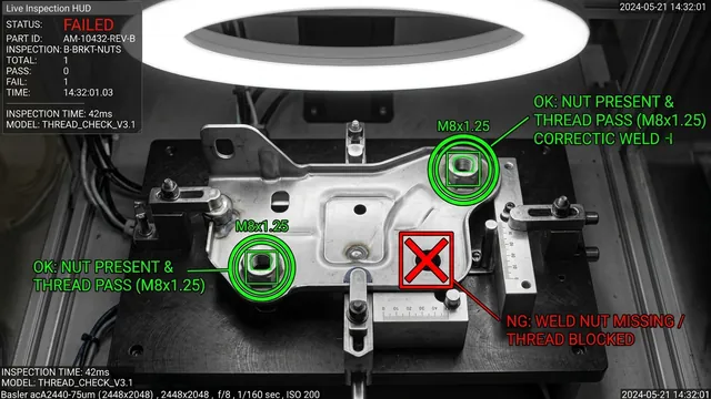
- Missing Nut / Incomplete Feed: The feeder hopper fails to dispense, the pneumatic delivery tube jams, or the nut falls off prior to electrode clamping. The welding electrode fires against bare sheet metal, leaving an unthreaded hole. If unaddressed, downstream chassis marriage stations cannot secure suspension crossmembers or battery packs.
- Inverted / Upside-Down Nut: The nut flips in the feeder track or magnetic gripper. The flat top face contacts the sheet metal while the welding projections point uselessly into open space. While the resistance welder may melt slight surface contact, there is zero metallurgical fusion. Downstream, when a pneumatic torque wrench applies 80 Nm of fastening torque, the nut snaps clean off, requiring emergency line stoppages.
- Thread Spatter Fouling & Clogging: Excessive welding current or misaligned electrodes cause liquid steel expulsion (spatter) to blast into the internal female threads. Once cooled, the spatter balls fuse to the pitch, causing automated bolt-runners to cross-thread, seize, or strip the bolt shank.
- Misalignment, Nut Skew, and Double-Feeding: Two nuts feed simultaneously, or a nut is welded at an angle (>3° tilt relative to panel normal), preventing bolts from entering perpendicular thread axes.
Evaluating Automated Optical Inspection for Your Line?
Send us 5–10 sample images of your OK/NG parts or share your cycle-time and lighting constraints. Our Computer Vision architects will benchmark detection feasibility within 48 hours—or join a 20-minute technical scoping session.
Illumination Physics: Darkfield vs. Brightfield on Oily Sheet Metal
Achieving reliable machine vision on stamped automotive sheet metal is notorious for optical noise. Stamped components are coated in rust-inhibiting stamping oils, forming specular puddles that act like chaotic liquid mirrors. Furthermore, galvanized coatings (such as electro-galvanized or hot-dip zinc-iron alloys like Galvanneal) exhibit microscopic grain textures and crystal spangles that scatter light unpredictably.
If an engineer positions a conventional brightfield light directly above the fastener, the flat sheet metal reflects maximum illumination straight into the camera lens. The sensor saturates with blinding white glare, obliterating the subtle dark edges of the fastener hole and the microscopic threads.
The Darkfield Optical Solution
To inspect weld nuts with sub-millimeter reliability, vision systems employ low-angle directional darkfield illumination (typically 10° to 25° from the panel surface) or multi-quadrant low-angle LED ring arrays.
- Specular Rejection: Light emitted at a grazing angle hits the flat sheet metal and oily film, reflecting away at the complementary grazing angle according to Snell's law of reflection. None of this light enters the perpendicular camera lens; consequently, the oily background appears virtually black.
- Edge & Thread Highlighting: When the low-angle light strikes vertical or inclined surfaces—such as the chamfered corners of the nut, the protruding welding tabs, or the internal helical thread ridges—it scatters upward directly into the lens. The fastener perimeter, thread crests, and projection nibs blaze with intense, high-contrast white illumination.
- Wavelength Selection: High-intensity monochromatic red (630nm) or near-infrared (850nm) LEDs are preferred. Red/NIR wavelengths minimize sensitivity to oily hydrocarbon sheens and provide superior penetration through residual oil films without causing rainbow diffraction patterns.
When combined with custom polarizing filters and narrow-band optical bandpass filters matched to the illumination wavelength, the vision camera becomes completely immune to the blinding ambient light flashes generated by adjacent robotic MIG, spot, or projection welding cells.
Fastener Inspection Parameter Matrix
The engineering matrix below outlines operational parameters, optical configurations, and inspection tolerances for common automotive BIW fastener applications:
| Inspection Metric | DIN 928 Square Nut | DIN 929 Hexagonal Nut | Threaded Weld Stud | Pierced Clinch Nut |
|---|---|---|---|---|
| Primary Target Locations | Rocker panels, frame rails | Subframes, suspension towers | Firewall, floor pan brackets | High-strength B-pillars |
| Typical Fastener Size | M6 × 1.0 to M12 × 1.75 | M8 × 1.25 to M14 × 2.0 | M5 to M8 (Length 15–40mm) | M6 to M10 flanged |
| Camera Configuration | 12.3 MP Global Shutter CMOS | 5.0 MP Global Shutter CMOS | Dual-camera 90° profile view | 12.3 MP Telecentric Area Scan |
| Illumination Angle | 15° Low-Angle Darkfield Ring | 4-Quadrant Low-Angle Darkfield | Backlight Profile + Coaxial | Multi-angle Diffuse Darkfield |
| Inversion Verification Method | Corner projection nib detection | Counterbore chamfer & face ring | Thread base flange presence | Serration ring displacement |
| Allowable Angular Tilt | ≤ 2.0 degrees | ≤ 1.5 degrees | ≤ 1.0 degree perpendicularity | ≤ 1.5 degrees |
| Inspection Cycle Time | 180 ms per fastener ROI | 150 ms per fastener ROI | 220 ms per fastener ROI | 160 ms per fastener ROI |
| Target Detection Accuracy | > 99.99% (Zero escape) | > 99.99% (Zero escape) | > 99.98% | > 99.99% |
Computer Vision Architecture & Edge Inference Engine
Automated fastener inspection in automotive BIW must resolve complex spatial geometry across stamped parts that vary due to batch-to-batch metal elasticity (springback) and robotic positioning repeatability. An effective vision pipeline merges deep learning object detection with deterministic metrological algorithms.
Our production vision systems employ a hierarchical, multi-stage processing architecture:
Stage 1: Part Alignment & Dynamic ROI Normalization
When the BIW panel or sub-assembly is clamped into the inspection fixture, high-resolution cameras acquire images under pulsed LED strobe illumination. Before evaluating fasteners, the system must register the panel:
- Fiducial Hole / Edge Localization: Using geometric pattern matching or a lightweight edge CNN, the system locates stamped reference tooling holes (pin locator holes).
- Affine Coordinate Transform: By measuring the spatial displacement and rotation (Δx, Δy, Δθ) of the tooling holes relative to nominal CAD coordinates, all fastener inspection Regions of Interest (ROIs) are mathematically translated and rotated. Even if the robotic handling gripper deposits the panel 3 mm off-center, every fastener ROI lands squarely on its target nut.
Stage 2: Fastener Classification via TensorRT Deep Learning
Each cropped fastener ROI is fed into a specialized multi-task convolutional neural network (CNN) optimized with NVIDIA TensorRT. The network simultaneously performs classification and semantic defect segmentation:
- Presence & Class Verification: Validates whether a fastener is present, and whether the correct part number was fed (e.g., confirming an M10 hex nut was not loaded into an M8 square nut station).
- Inversion / Polarity Verification: Inspects the distinctive morphological features of the nut's top face vs. bottom welding face. On a correctly oriented nut, the top face exhibits a pronounced concentric lead-in counterbore chamfer, smooth bearing surfaces, and manufacturer grade markings. On an inverted nut, the system detects the protruding projection weld bosses, lack of counterbore chamfer, or raw pilot rings designed to seat in the sheet hole.
Fastener Inspection Operational Specifications
The vision system runs deterministic feature extraction and template verification against CAD coordinate master files. The operational parameters table below highlights the inspection criteria:
| Inspection Criterion | Tolerance Threshold | Action on Out-of-Spec |
|---|---|---|
| Fastener Presence | 100% (Binary Presence / Absence) | Immediate robot fixture cycle abort; operator visual alert on HMI. |
| Thread Integrity (Pitch & Spatter) | ≥ 98% concentric circular thread visibility | Flag part for pneumatic thread-cleaning rework station. |
| Nut Axial Tilt | ± 2.5 degrees relative to sheet metal normal | Eject to automated weld rework queue before robotic bolting. |
| Total Station Latency | ≤ 42 ms per bracket fixture | Deterministic PLC handshake before robot clamp release. |
Stage 3: Sub-Pixel Thread & Spatter Metrology
Deep learning provides unmatched resilience against oil streaks and ambient variations, but metrological verification requires sub-pixel mathematical precision. To confirm internal threads are clean and uninhibited by welding spatter:
- Inner Minor Diameter Measurement: Using polar coordinate unwrapping and radial gradient peak detection, the system traces the inner crests of the internal thread profile.
- Fourier Spatial Frequency Analysis: The helical thread ridges generate a distinct periodic spatial frequency when unwrapped radially. If weld spatter has bridged the threads or melted the pitch, the periodic frequency peak collapses, flagging a stripped or spatter-fouled thread immediately.
- Concentricity & Perpendicularity: The vision engine measures the distance between the center of the inner threaded hole and the stamped outer hole in the sheet metal, verifying that angular tilt does not exceed ±1.5°.
For custom engineering consultations on implementing high-speed metrology and edge classification, review our Computer Vision development services and explore our proven deployments in Automotive Manufacturing AI.
Industrial Robotic Deployment: Fixed Gantry vs. Robot End-Effector
Depending on the geometry of the automotive stamping, machine vision systems for weld nut inspection are deployed in one of two configurations:
Configuration A: Fixed Multi-Camera Gantry Inspection
Ideal for planar stamped sub-assemblies such as floor pans, seat crossmembers, and firewall panels. An array of 4 to 16 industrial cameras equipped with compact low-angle darkfield illuminators is mounted above the fixture. When the panel is clamped, all cameras trigger simultaneously. The entire panel—housing up to 40 fasteners—is inspected in parallel within 300 to 500 milliseconds, allowing zero impact on line cycle times.
Configuration B: Robot End-Effector 3D Eye-in-Hand Vision
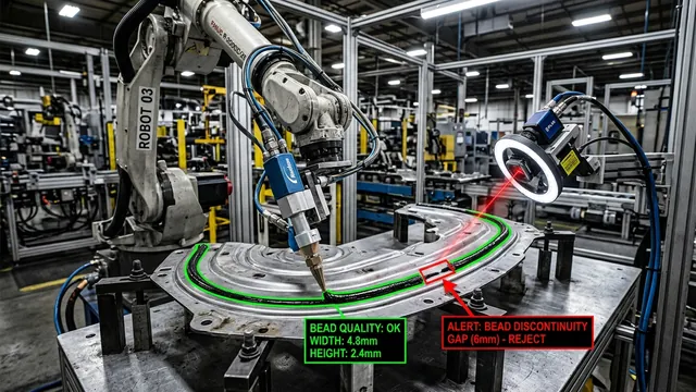
For deep, multi-dimensional structural assemblies such as complete vehicle underbodies, engine compartments, or welded chassis frames, line-of-sight obstruction makes fixed cameras impractical. In this setup, an IP67-rated industrial camera, telecentric lens, and integrated multi-quadrant darkfield ring light are mounted directly to the wrist of a 6-axis industrial robot (e.g., FANUC, KUKA, or ABB).
The robot follows an optimized path, pausing for 120 ms over each fastener cluster. The vision system fires high-speed strobes on-the-fly or during brief settles, streaming inspection status back to the robot controller to dynamically confirm part acceptance before indexing.
PLC & Fieldbus Integration: Zero-Jitter Profinet & EtherNet/IP
In high-speed automotive stamping and assembly, vision data must link directly to the machine safety and automation loop. If a weld nut is missing, the cell cannot simply log an entry in a database—it must physically inhibit the robot from advancing the carrier into the downstream multi-stage welding press.
Fieldbus Protocol Handshake Architecture
Our edge inspection computers communicate with plant automation using industrial PC fieldbus master/slave cards running Profinet (RT and IRT) or EtherNet/IP with CIP Sync:
- Direct Cyclic Data Exchange: At every 4ms fieldbus cycle, the vision system maintains a continuous heartbeat with the main line PLC (e.g., Siemens S7-1500F or Rockwell ControlLogix 5580).
- Hardware Part Inspection Handshake:
- PLC sets Inspection_Request = TRUE and transmits part variant identifier (e.g., Sedan vs. SUV chassis model code).
- Vision system loads variant CAD template, confirms strobe drivers charged, and issues Ready_To_Trigger = TRUE.
- PLC triggers physical hardware strobe via 24V isolated PNP input.
- Vision computer executes pipeline, evaluates all fastener ROIs, and returns individual pass/fail bits plus fault location bytes:
- Overall_Station_Pass (Bit)
- Fastener_Defect_Bitmap[0..31] (Bit array locating exact defective nut position)
- Fault_Type_Code (1 = Missing, 2 = Inverted, 3 = Spatter Fouled, 4 = Tilted)
- PLC verifies valid data, clears Inspection_Request, and unlocks mechanical clamps.
If an inverted or missing nut is detected, the PLC immediately triggers an automated part reject routine: the welding cell stops, pneumatic markers spray colored paint onto the defective fastener location for operator identification, and the assembly is automatically diverted to an offline manual rework station.
To learn how we design deterministic hardware and edge software stacks for extreme plant environments, see our overview of Edge AI hardware engineering.
Defeating Welding Flash: Optical Bandpass Filtering
One of the harshest environmental hurdles in an automotive welding shop is the intense electromagnetic and optical noise created by surrounding resistance spot welding guns and robotic GMAW (MIG) arc welding torches. An arc welding flare generates broadband white light exceeding 100,000 lux, capable of blinding vision sensors tens of meters away.
To operate reliably within inches of active welding robots, our vision stations utilize an optical filtering fortress:
- Narrow-Band Optical Bandpass Filters: High-transmission dielectric interference filters (e.g., 850nm NIR with a full-width at half-maximum (FWHM) of ±10nm) are mounted on every camera lens. Over 98% of ambient white, ultraviolet, and visible arc flash is optically blocked from reaching the CMOS sensor.
- Microsecond Strobe Overdrive: Instead of operating LEDs in continuous mode, pulsed LED drivers overdrive high-power LED dies with up to 500% of nominal current for short microsecond bursts (e.g., 20 µs to 50 µs). During this microsecond exposure, the LED intensity dwarfs any residual ambient light by an order of magnitude.
- Global Shutter Synchronization: Global shutter sensors expose all pixels simultaneously, eliminating the horizontal banding and tearing artifacts that rolling shutters experience when exposed to fluctuating AC welding arcs.
ROI and Quality Impact on Automotive BIW Lines
Automating fastener inspection delivers profound financial and operational returns for automotive OEMs and tier-1 stamping suppliers:
- Zero Field Recalls for Structural Fasteners: Weld nuts securing suspension links, subframes, seat belts, and child safety anchorages (ISOFIX/LATCH) are safety-critical Tier-1 items. Catching 100% of missing or weakly fused inverted nuts prevents catastrophic mechanical failure and regulatory safety recalls.
- E-Coat Paint Shop Protection: Once a BIW body enters the cathodic dip painting bath (E-coat), baking ovens cure the resin at over 180°C. Adding or replacing a weld nut after painting destroys the protective coating, initiates premature galvanic corrosion, and requires hours of hazardous manual grinding and refinishing. Inline vision eliminates painted defects entirely.
- Optimizing Overall Equipment Effectiveness (OEE): Automatic torque guns in downstream trim and chassis lines frequently lock up when encountering missing or spatter-fouled nuts. A 3-minute line halt on a 60-JPH (jobs per hour) line represents a loss of 3 fully manufactured vehicles. Eliminating fastener-induced torque faults protects production throughput.
Ready to deploy zero-defect fastener verification on your stamping or welding lines? Contact the AdaptNXT engineering team to discuss cycle times, optical requirements, and PLC integration.
Frequently Asked Questions (FAQ)
How does the system distinguish an upside-down weld nut from a correct one when both are square?
While the outer perimeter of a DIN 928 square nut is identical from both sides, the functional faces are structurally distinct. The bottom welding face features four raised projection bosses (nibs) designed to melt into the sheet metal, whereas the top bearing face features a smooth planar surface and a machined counterbore lead-in chamfer around the threaded bore. By using low-angle darkfield illumination, our computer vision system specifically highlights the presence or absence of these projection nibs and the reflective signature of the top-face chamfer, achieving 100% orientation verification.
Can machine vision detect weld spatter inside female threads before bolting?
Yes. By pairing coaxial on-axis illumination with high-resolution telecentric or narrow-angle lenses, light travels directly down into the threaded cylinder. When female threads are clean, the system captures a uniform, concentric pattern of helical thread crests and roots. When molten weld spatter invades the bore, it forms irregular specular nodules that break thread concentricity. High-speed mathematical contour analysis and sub-pixel edge detection flag thread cross-sectional occlusions as small as 0.2 mm.
Does oil or lubricant on the stamped sheet metal cause false rejects?
No. Stamping draw lubricants cause severe false rejects under direct brightfield lighting due to reflective glare puddles. However, our systems utilize low-angle darkfield illumination (10° to 20° incident angle) paired with cross-polarizing filters and near-infrared (850nm) wavelengths. The oily planar sheet metal directs specular reflections away from the camera lens, rendering the background dark while making the physical metal edges of the fastener stand out sharply regardless of oil pooling.
What is the typical cycle time to inspect a complete stamped sub-assembly?
In a fixed multi-camera inspection gantry, all cameras strobe and acquire images simultaneously within 10 to 30 milliseconds. Deep learning inference and sub-pixel metrology across 20 to 40 fastener ROIs run concurrently on an industrial edge GPU (such as NVIDIA Jetson AGX Orin or industrial RTX workstations) in 150 to 350 milliseconds. The entire PLC inspection handshake completes well under 500 milliseconds, fitting seamlessly within high-speed automotive cycle times.
How does the system interface with existing plant PLCs and SCADA networks?
The vision computer integrates directly via hardware industrial fieldbus cards supporting Profinet RT/IRT, EtherNet/IP, or Modbus TCP. It exchanges deterministic I/O words with Siemens, Rockwell Allen-Bradley, Beckhoff, or Mitsubishi PLCs. Additionally, high-level inspection logs, error code breakdowns, and timestamped defect images are transmitted to plant SCADA and MES architectures via OPC UA and MQTT protocols.