
In modern automotive manufacturing, structural adhesives and elastomeric sealants have largely replaced traditional mechanical rivets, spot welds, and rubber gaskets. From structural polyurethane bonding windshield glass into vehicle chassis to airtight silicone beads sealing high-voltage EV battery pack enclosures, automated fluid dispensing is fundamental to vehicle safety, acoustic damping, and crashworthiness. Yet dispensing viscous fluids at robotic speeds exceeding 500 mm/s is inherently volatile—pump cavitation, nozzle clogs, temperature-driven viscosity swings, and robotic acceleration spikes constantly threaten bead continuity.
When a sealant bead experiences a 5 mm void along an EV battery tray lid, moisture inevitably ingresses into the battery pack, triggering galvanic corrosion and disastrous high-voltage shorts. If a windshield bonding bead thins out, cabin water leaks, wind whistling, and structural roof crush failure occur during vehicle rollover accidents. In this comprehensive technical guide, we examine how advanced computer vision—spanning 2D high-speed imaging and 3D laser triangulation profilometry—delivers continuous, real-time quality verification on high-throughput automotive production lines.
Evaluating Automated Optical Inspection for Your Line?
Send us 5–10 sample images of your OK/NG parts or discuss your cycle-time and lighting constraints. Our Computer Vision architects will benchmark detection feasibility within 48 hours—or join a 20-min zero-pitch technical scoping session.
Key Takeaways
- Airtight IP67/IP69K Ingress Protection: Real-time bead inspection is the primary quality gate ensuring EV battery pack lids prevent moisture ingress and catastrophic electrical thermal events.
- Overcoming the "Black-on-Black" Optical Dilemma: Dispensing black polyurethane sealant onto black cathodic e-coat or dark windshield ceramic frit renders 2D grayscale cameras useless; 3D laser triangulation resolves height profiles purely through laser geometric triangulation.
- Volumetric Metrology: True quality verification requires measuring cross-sectional area, height, width, and position, mathematically integrating profile slices along the robot path to compute continuous dispensed volume.
- Trailing-Head Robotic Integration: Mounting multi-laser vision heads directly onto the robotic dispensing wrist 30 mm behind the nozzle enables instantaneous flaw detection and immediate process stoppage before substrate joining.
- Closed-Loop Dispensing Feedback: Feeding bead width and height drift metrics back to dispensing controllers (e.g., Atlas Copco, Nordson) enables automated pump pressure and flow-rate compensation.
The Critical Role of Adhesive & Sealant Beads in Automotive Manufacturing
The transition toward lightweight vehicle construction, aerodynamic drag reduction, and electric powertrain packaging has driven unprecedented reliance on structural chemical bonding. Automotive OEMs apply hundreds of meters of adhesive and sealant across distinct production domains:
- EV Battery Pack Enclosure Sealing: Electric vehicle battery trays (whether cast aluminum, extruded profiles, or stamped sheet steel) must achieve certified IP67 or IP69K ingress ratings. A continuous, uniform bead of single- or two-component polyurethane, room-temperature vulcanizing (RTV) silicone, or thixotropic butyl sealant is laid along the perimeter flange before robotic bolting. Any void, micro-bubble channel, or localized necking permits moisture entry, destroying the multi-thousand-dollar battery array.
- Automotive Glass & Windshield Direct Glazing: Windshields and panoramic glass roofs are not merely cosmetic windows; they are load-bearing structural members contributing up to 30% of the vehicle cab's torsional rigidity. A high-modulus polyurethane bead must be laid around the black ceramic enamel frit band with tight geometric tolerance (±0.5 mm in width and ±0.7 mm in height).
- Body-in-White (BIW) Door Hem Flanges & Outer Panels: Anti-flutter mastic adhesives and hem flange epoxy sealants join inner and outer door skins, hoods, and liftgates. These materials prevent sheet metal vibration, block atmospheric road salt intrusion, and prevent panel corrosion.
The Anatomy of Dispensing Failure Modes
Automated fluid dispensing systems operate under severe dynamic forces. High-pressure progressive cavity pumps or servo-driven piston dispensers push viscous chemical pastes through narrow nozzles (diameters between 2.0 mm and 10.0 mm). A variety of physical disruptions introduce critical bead flaws:
- Bead Gaps & Interruptions (Voids): Air pockets entrained in the adhesive drum, pump cavitation, or momentary nozzle clogs interrupt fluid flow, creating unsealed gaps ranging from fractions of a millimeter to several centimeters.
- Bead Necking & Thinning: If the 6-axis robot accelerates through a corner faster than the dispensing pump can ramp pressure (or if adhesive viscosity spikes due to temperature drop), the bead stretches and thins. The reduced cross-sectional area lacks sufficient volume to bridge the manufacturing gap between mating substrates.
- Excessive Pooling & Slumping: Robot deceleration at tight radii, over-pressurization, or low fluid viscosity causes adhesive pooling. When panels are clamped, excess adhesive squashes outward onto cosmetic exterior panels or interior passenger trim, requiring costly chemical solvent scrubbing.
- Positional Drift & Snake Tracking: Part dimensional variation or robot path programming drift causes the bead to wander off the target flange center, risking partial bond contact or spillage off structural edges.
- Internal Air Bubbles: Entrapped micro-bubbles that break the surface during curing create continuous capillary leak paths across the sealing barrier.
2D Vision vs. 3D Laser Triangulation Profilometry
Historically, production lines attempted to inspect sealant beads using standard 2D grayscale or color industrial cameras mounted overhead. While 2D systems remain viable for specific high-contrast scenarios, they suffer fundamental physical limitations that make 3D profiling mandatory for safety-critical applications.
The "Black-on-Black" Optical Bottleneck
In direct glazing and EV battery manufacturing, the chemical adhesive is typically carbon-black-pigmented polyurethane or dark silicone. The substrate onto which it is dispensed is frequently black cathodic dip coating (E-coat), dark structural carbon composite, or the pitch-black ceramic enamel frit band printed on automotive glass. Under standard 2D illumination, both the adhesive bead and the substrate absorb visible light equally. Grayscale contrast is virtually nonexistent, rendering traditional pixel intensity thresholding and edge detection completely ineffective.
The 3D Laser Triangulation Principle
3D laser line profile sensors eliminate reliance on surface color or contrast by measuring physical three-dimensional geometry. The sensor projects a calibrated laser line (typically blue 405nm) across the sealant bead. An internal CMOS sensor, mounted at a calibrated triangulation angle θ according to the Scheimpflug optical condition, observes the laser line.
When the laser passes over the raised profile of the sealant bead, the projected line physically shifts across the sensor pixels proportional to the bead's elevation: Δz = Δx' / (M · sin θ), where M is optical magnification. By capturing thousands of profile slices per second (frequencies from 2,000 Hz to 10,000 Hz) as either the robot head or the substrate moves, the system constructs a dense, calibrated 3D heightmap.
From this 3D point cloud, the inspection software extracts true physical metrics independent of surface color:
- Absolute bead height (Z-profile)
- Bead width at defined reference thresholds (X-profile)
- Continuous cross-sectional area (mm²)
- Transverse position relative to part flange edges (Y-offset)
Sensor Architecture Comparison Matrix
The table below provides a detailed technical comparison of the sensor modalities used for automated adhesive and sealant bead inspection on automotive lines:
| Performance Metric | 2D Area Scan Vision | Single-Line 3D Laser Triangulation | Multi-Laser / Circular 3D Profiler | Coaxial Confocal Sensor |
|---|---|---|---|---|
| Measured Geometric Dimensions | 2D Planar (Width, Position, Continuity) | 3D (Width, Height, Area, Volume) | 3D Omni-directional (Zero blind spots) | High-precision 1D/3D Point Depth |
| Contrast Sensitivity | High (Fails on black-on-black) | Zero (Immune to color & contrast) | Zero (Immune to color & contrast) | Zero (Immune to color & contrast) |
| Optimal Optical Wavelength | Polarized White or Red (630nm) | Blue Laser (405nm) | Multi-Blue Laser (405nm / 450nm) | Broadband White Chromatic |
| Z-Height Resolution | Not measurable | ± 5.0 µm to ± 15.0 µm | ± 8.0 µm to ± 20.0 µm | ± 0.1 µm (Sub-micron) |
| Maximum Robotic Tracking Speed | Up to 1,000 mm/s | 500 – 800 mm/s (Linear only) | Up to 800 mm/s (Omnidirectional) | 150 – 250 mm/s |
| Corner & Curve Trajectory Tracking | Fixed overhead FOV only | Requires robot wrist rotation alignment | Continuous 360° tracking without wrist rotation | Limited field of view |
| Hardware Deployment Complexity | Low (Standard lighting & lens) | Moderate (Calibrated triangulation head) | Engineered robotic wrist integration | High (Fiber-optic optical head) |
| Cost Profile | $ (Low) | $$$ (Medium-High) | $$$$ (High-End Automotive Spec) | $$$$ (Specialized R&D) |
The Real-Time Inspection Pipeline & Volumetric Mathematics
True inline inspection requires processing raw profile streams in real time without buffering large data bursts that introduce latency. When a dispensing robot glides along an automotive windshield periphery, the inspection engine mounted 30 mm behind the dispensing tip must evaluate every profile slice within microseconds.
Mathematical Formulation of Volumetric Continuity
At each acquisition timestamp $, the laser sensor captures a discrete cross-sectional profile curve (x)$ representing the height of the bead across the transverse axis $.
- Substrate Baseline Leveling: The algorithm identifies the flat substrate regions immediately flanking the bead on the left ( \in [x_{L1}, x_{L2}]$) and right ( \in [x_{R1}, x_{R2}]$). A robust linear regression fits the substrate baseline plane: ${base}(x) = m \cdot x + c$$ Subtracting this baseline normalizes the profile against substrate tilt or panel curvature.
- Width & Peak Height Extraction: The maximum bead height $ is evaluated as: $ = \max_x [z_k(x) - z_{base}(x)]$$ The bead width $ is measured at a predetermined threshold percentage (typically 10% or 20% of peak height) using sub-pixel interpolation across the rising and falling edges.
- Cross-Sectional Area Integration: The cross-sectional area $ of the fluid slice is calculated by numerical integration: $ = \int_{x_{left}}^{x_{right}} [z_k(x) - z_{base}(x)] \, dx$$
- Path Volumetric Integration: Given the instantaneous robot toolpath velocity $ and sampling period $\Delta t$, the discrete travel increment is $\Delta s_k = v_k \cdot \Delta t$. The total dispensed volume $ over path length $ is continuously accumulated: $ = \sum_{k=1}^{N} A_k \cdot \Delta s_k$$ If $ drops below the minimum threshold {min}$ for a consecutive travel distance exceeding 2.0 mm, an instantaneous VOID_DETECTED fault is flagged.
Robotic Sealant Dispensing Inspection Specifications
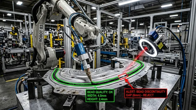
The vision system processes laser triangulation profile slices synchronized with the robot arm Tool Center Point (TCP) velocity. Here is the operational specification framework:
| Parameter | Target Dimension & Tolerance | Quality Risk Mitigated |
|---|---|---|
| Bead Width | 4.8 mm ± 0.5 mm | Prevents adhesive squeeze-out onto sensitive battery electrical contacts. |
| Bead Height | 2.4 mm ± 0.3 mm | Ensures required IP67 compression seal without excessive flange bolting force. |
| Bead Continuity (Gaps) | Zero tolerance (max allowable gap < 0.5 mm) | Eliminates water intrusion pathways and acoustic cabin leaks. |
| Profile Sampling Frequency | 2,000 Hz laser profile slices | Enables sub-millimeter longitudinal tracking at robot speeds up to 500 mm/sec. |
To discover how AdaptNXT designs high-frequency real-time edge processing nodes, explore our Edge AI development solutions and learn more about our comprehensive Computer Vision engineering capabilities.
Inline Trailing-Head Robot Deployment
The mechanical architecture of a sealant bead inspection system dictates its detection capability. In automotive production, two deployment topologies predominate:
1. Eye-in-Hand Trailing Vision Head (In-Process)
The vision sensor is mounted directly to the robotic applicator arm, rigidly affixed 30 mm to 50 mm behind the dispensing nozzle. As the robot articulates along the complex 3D contours of a car body or windshield, the sensor follows the newly deposited bead within milliseconds of extrusion.
The Multi-Laser Advantage: When a robot navigates tight 90° corners, a single fixed laser line sensor risks having the bead exit its field of view unless the robot continually rotates its sixth axis. To solve this, advanced automotive vision heads employ tri-laser or circular 360° laser arrays. Three intersecting laser lines surround the dispensing tip; software dynamically selects the optimal laser line perpendicular to the instantaneous motion vector, maintaining continuous inspection regardless of direction without demanding robot wrist repositioning.
2. Post-Process Fixed Multi-Camera Gantry
For smaller sub-assemblies or high-speed stamping operations, the bead is dispensed first, and the part is transferred to a dedicated optical inspection gantry. A bank of high-resolution 2D cameras paired with multi-spectral lighting or scanning 3D line profilers captures the complete bead path in a single 1.5-second pass. While this approach decouples inspection hardware from robot weight limits, it cannot halt dispensing mid-process if a catastrophic pump failure occurs.
Industrial Connectivity: Dispenser, Robot, and Safety Interlocks
A sealant bead inspection system operates at the nexus of multiple high-speed industrial controllers: the 6-axis robot controller (FANUC, KUKA, ABB), the fluid dispensing metering controller (Atlas Copco/SCA, Nordson, Graco), and the station safety PLC.
Real-Time Control Loop Interfacing
Our edge inspection computers communicate with line equipment across three operational levels:
- Discrete High-Speed Safety Interlocks (Hardware I/O): An opto-isolated 24V hardware line connects directly to the robot emergency stop (E-stop) or feed-hold circuit. If an unrecoverable bead gap (>5 mm) is detected on an EV battery pack enclosure, the vision computer drops the safety line in under 5 ms, freezing robot motion before the defective part can be joined to its mating half.
- Industrial Ethernet Fieldbus (Profinet / EtherNet/IP): Transmits continuous quality words every 10 ms:
- Current bead width & height (mm × 100)
- Volumetric area deviation (%)
- Accumulated dispensed length (mm)
- Status bitmap (Nozzle Clog, Slumping, Off-track, Bubble Detected)
- Closed-Loop Dispensing Volume Compensation: When automated vision detects a progressive trend toward bead thinning (caused by adhesive cooling in supply hoses), the vision system transmits proportional correction offsets to the dispensing controller over Ethernet. The dosing unit automatically increases piston velocity or gear pump RPM by 3–5%, restoring nominal bead dimensions without human operator intervention.
To learn more about connecting AI computer vision systems directly into industrial robotics and factory control systems, review our Manufacturing AI Solutions.
Error Handling, Bubble Detection, and False Positive Mitigation
Automated sealant inspection must overcome harsh plant-floor optical disturbances. Highly viscous sealants frequently have high surface gloss, producing intense specular reflections that can distort laser peak detection on traditional CMOS sensors.
Our vision architectures deploy multi-tiered algorithmic defenses:
- High Dynamic Range (HDR) Laser Peak Extraction: Sealant materials range from matte carbon-black to ultra-glossy translucent silicones. Our 3D sensors use dual-exposure HDR CMOS pixels combined with Center-of-Gravity (CoG) peak detection algorithms to extract true laser line centerlines without blooming artifacts.
- Micro-Bubble vs. True Void Discrimination: A tiny surface dimple caused by an outgassing solvent bubble must not be confused with a structural bead break. The inspection engine applies temporal and volumetric thresholds: a flaw is classified as a critical gap only if the cross-sectional area remains sub-nominal for a user-defined physical length (e.g., > 1.5 mm). Smaller surface pockmarks are logged as cosmetic warnings without halting the line.
- Automatic Splatter & Debris Masking: If stray metal chips or stamping oil droplets sit near the flange edge, morphological filtering masks out isolated point clusters outside the continuous convex hull of the bead profile.
ROI and Quality Impact on Automotive Assembly Lines
Automated inline sealant and adhesive bead verification provides measurable, bottom-line returns for automotive manufacturers:
- 100% Elimination of Water Leak Warranty Claims: Windshield water ingress and cabin dampness represent some of the highest-cost warranty repair claims for automotive dealerships, requiring complete interior carpet removal and dashboard disassembly. Zero-defect bead inspection guarantees hermetic perimeter integrity before glass cures.
- Eliminating Scrapped EV Battery Enclosures: Once an EV battery lid is bolted down and the adhesive begins its chemical cross-linking cure, the pack cannot be opened without destroying the composite enclosure or bending the sealing flange. Inline trailing inspection guarantees 100% bead integrity before mechanical fasteners are torqued down.
- Material Consumption Optimization: Automotive plants apply tens of thousands of gallons of expensive structural adhesives annually. Closed-loop vision feedback eliminates "over-dispensing"—a common practice where operators intentionally overfill beads to compensate for unknown dispensing fluctuations—yielding adhesive material savings of 8% to 14%.
Looking to deploy high-precision sealant bead inspection or integrate 3D laser profilers onto your robotic dispensing cells? Contact our computer vision team to review your CAD files and application tolerances.
Frequently Asked Questions (FAQ)
Why can't standard 2D industrial cameras reliably inspect black polyurethane on black E-coat?
Both black polyurethane adhesive and black cathodic dip coating (E-coat) have virtually identical optical absorption spectra in the visible and near-infrared ranges. Under conventional 2D illumination, both surfaces reflect minimal light, resulting in a low-contrast image where grayscale pixel intensity values for the bead and the sheet metal blend together. Furthermore, 2D cameras are physically incapable of measuring bead height or cross-sectional volume. 3D laser triangulation overcomes this by projecting a calibrated laser line, calculating height profiles purely based on geometric triangulation regardless of color or contrast.
How does the system inspect beads around tight 90-degree corners on windshield glass?
In traditional single-laser profile systems, navigating tight corners requires the robot to reorient its 6th wrist axis to keep the laser perpendicular to the bead path, which slows robotic cycle times. Modern production systems solve this using multi-laser or circular 360-degree laser sensor heads. These sensors project three intersecting laser lines around the dispensing nozzle. As the robot transitions into a corner, the vision software automatically switches to the laser line that maintains an optimal orthogonal angle to the instantaneous motion vector, enabling continuous inspection at speeds up to 800 mm/s without robot wrist rotation.
What is the minimum bead void size that 3D laser triangulation can detect?
Modern high-frequency 3D laser triangulation sensors operate at profile sampling rates between 4,000 Hz and 10,000 Hz. When moving at typical robotic dispensing speeds of 400 mm/s to 500 mm/s, the sensor captures a profile slice every 0.05 mm to 0.1 mm along the travel path. Combined with a vertical Z-height resolution of ±10 µm, the system reliably detects micro-voids, necking, and air gaps as small as 0.2 mm in length and width.
Can the vision system automatically adjust dispensing pump pressure if the bead begins thinning?
Yes. Through closed-loop industrial Ethernet communication (Profinet or EtherNet/IP), the vision engine continuously streams moving average cross-sectional area and width metrics to the adhesive dosing controller (such as Atlas Copco, Nordson, or SCA). If material viscosity changes due to temperature fluctuations, the dispensing controller dynamically ramps motor speed or valve stroke up or down to keep bead volume within nominal specifications, eliminating manual re-calibration.
How does the system handle reflective or glossy sealants without blinding the camera?
Freshly dispensed sealants often have an oily or glossy liquid finish that creates intense specular highlights when hit by laser light. Our industrial 3D profile sensors utilize high dynamic range (HDR) CMOS imaging arrays that capture multiple exposures per profile line. Specialized Center-of-Gravity (CoG) peak detection algorithms pinpoint the true centroid of the reflected laser curve even in the presence of localized sensor saturation, ensuring clean 3D profile reconstruction without blooming.