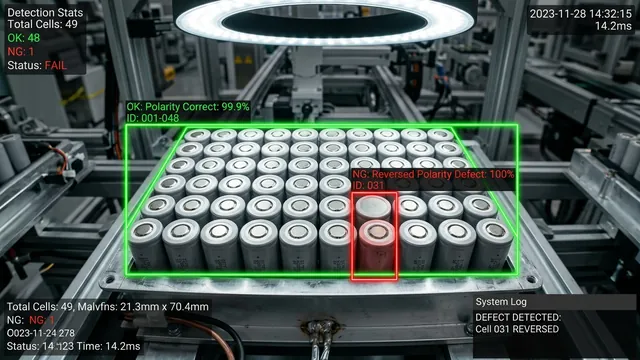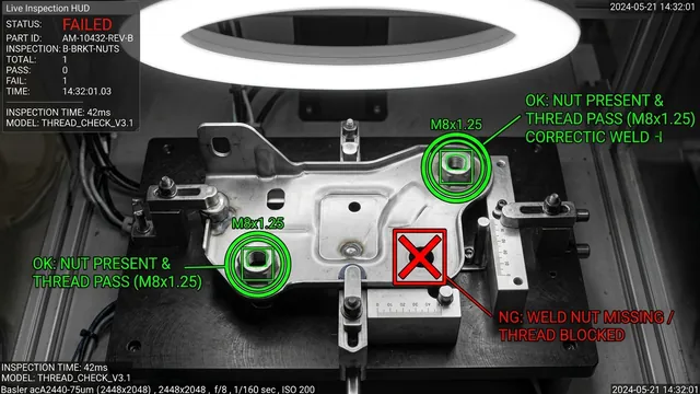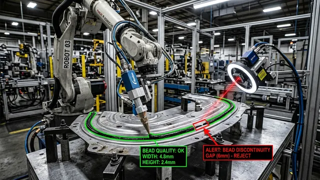

Modern high-speed industrial packaging, bottling, and discrete manufacturing facilities operate at blistering velocities. Production lines routinely discharge small confectioneries, pharmaceutical capsules, beverage bottle caps, stamped electrical terminals, and fastener hardware at throughput rates exceeding 150 to 300 units per second. At these operational dynamics, traditional sensing modalities—specifically photoelectric through-beam sensors, retro-reflective photocells, inductive proximity switches, and mechanical paddle counters—suffer from systemic failure modes that compromise inventory reconciliation and batch integrity.
Key Takeaways
- The Failure of Physical Beams: Conventional photoelectric sensors cannot decouple overlapping, tumbling, or touching parts (shingling), leading to undercounting rates of 1.5% to 5.0% on high-speed feeds.
- Sensorless AI Triggering: High-frame-rate global shutter cameras paired with virtual region-of-interest (ROI) optical triggers eliminate mechanical trigger jitter and optical switch wear.
- Sub-4ms Deterministic Inference: Lightweight convolutional backbones compiled with NVIDIA TensorRT INT8 precision execute on ruggedized industrial edge hardware in under 4 milliseconds per frame.
- Trajectory-Aware Multi-Object Tracking: Combining spatial tracking algorithms like ByteTrack and linear Kalman filters resolves temporary occlusions, orientation shifts, and free-fall trajectory bounces.
- Industrial Fieldbus Determinism: Direct hardware-level GPIO optoisolated pulsing and PROFINET/EtherNet/IP integration ensure exact real-time batch cutoffs and diverter gate actuation.
Summary Overview: Traditional Sensing vs. High-Speed Edge AI Vision
| Capability Parameter | Photoelectric / Fiber-Optic Sensors | Laser Micrometer Arrays | High-Speed Edge AI Vision System |
|---|---|---|---|
| Max Part Speed Handled | < 80 units/sec (unconstrained) | < 140 units/sec | 300+ units/sec (free-fall or belt) |
| Touching / Shingled Parts | Fails (registers as 1 single item) | Marginal (height contour ambiguities) | 100% Resolved via Watershed & Segmentation |
| Tumble & Part Bounce | Double-counts on trajectory oscillation | Subject to shadow profile artifacts | Kalman State Vectors filter out bounce |
| Defect / Foreign Object Flagging | None (binary optical break only) | Coarse dimensional 1D slicing | Simultaneous count, geometry & defect checks |
| Counting Accuracy SLA | 96.5% - 98.5% | 98.5% - 99.2% | > 99.98% |
| Integration Latency | < 0.5 ms | 1.0 - 2.5 ms | 2.8 - 4.0 ms (Inference + Tracking) |
When high-speed lines discharge discrete parts at 15 meters per second down gravitational chutes or across vibrating bowl feeder singulation tracks, parts frequently bunch together, rotate along three axes, or bounce erratically. A photoelectric sensor registers an electrical state transition whenever an opacity threshold is broken. If two candies touch end-to-end, the light beam remains continuously occluded, yielding a single count instead of two. Conversely, if a stamped metal bracket oscillates or flutters across the infrared beam path, the sensor register trips three times, erroneously logging ghost units. Over a 24-hour manufacturing shift producing millions of units, a 1.5% undercount forces overpacking to avoid regulatory penalties, eroding operating margins by hundreds of thousands of dollars.
To eliminate these systematic losses, manufacturing engineers are deploying high-speed industrial computer vision architectures powered by low-latency edge AI accelerators. By replacing binary optical tripwires with multi-megapixel global shutter CMOS sensors, nanosecond-precise LED strobe illumination, and embedded neural networks executing spatial multi-object tracking, plants achieve counting accuracies exceeding 99.98% at full production velocity. For enterprise engineering teams planning line modernizations, partnering with a specialized edge AI development company provides the turnkey hardware and software pipelines required to achieve sub-millisecond synchronization.
Evaluating Automated Optical Inspection for Your Line?
Send us 5–10 sample images of your OK/NG parts or share your cycle-time and lighting constraints. Our Computer Vision architects will benchmark detection feasibility within 48 hours—or join a 20-minute technical scoping session.
The Mechanics of Failure in Legacy Counting Hardware
Understanding why traditional sensors fail requires analyzing the physics of high-speed conveyance. Mechanical and optical sensors rely on three fragile assumptions: spatial separation between consecutive parts, predictable orientation, and linear velocity vectors. In high-speed packaging, none of these assumptions hold true.
1. Part Shingling and Edge Contiguity
In rotary packaging machines, candy wrapping lines, and blister feed chutes, parts frequently "shingle"—meaning the trailing edge of leading part Pn overlaps or physically abuts the leading edge of trailing part Pn+1. A standard fiber-optic through-beam sensor measures beam attenuation. Because there is no optical gap between the two objects, the photodiode amplifier maintains a high output state. The Programmable Logic Controller (PLC) high-speed counter card (e.g., Siemens S7-1500 TM Count or Rockwell 1756-HSC) detects only one falling edge trigger. In contrast, modern computer vision services utilize deep convolutional feature extractors and morphological segmentation masks that distinguish subtle surface boundary contours, identifying two distinct physical objects despite zero spatial separation.
2. Trajectory Bounce and Parallax Oscillation
When parts drop from a centrifugal feeder bowl onto a primary conveyor belt or free-fall through a vertical counting funnel, aerodynamic drag and mechanical restitution coefficients induce tumbling and micro-bouncing. As a non-spherical component (such as an automotive plastic retainer clip or pharmaceutical tablet) tumbles, its cross-sectional profile perpendicular to the sensor beam fluctuates dynamically. If the narrowest axis passes through the beam, light transmission can momentarily re-engage, pulsing the output pin and generating false increment signals. Standard debounce filters in PLC logic cannot solve this problem: increasing the filter debounce time causes genuine high-speed consecutive parts to be ignored, while decreasing it amplifies false double-counting.
3. Optical Cross-Talk, Dust Accumulation, and Thermal Drift
Industrial manufacturing plants are harsh optical environments. Vibratory bowl feeders shed micro-particulates, metal shavings, or sugar dust. Over continuous 8-hour production cycles, airborne debris deposits onto the optical lenses of photoelectric emitter-receiver heads. As optical transmission diminishes, the sensor drifts closer to its switching hysteresis margin, causing intermittent trigger drops or sensitivity saturation. Optical sensors also suffer from ambient light contamination, especially when high-frequency overhead factory lighting or adjacent robotic safety laser scanners induce optical crosstalk on photodiode receivers.
The Optical Architecture: Freezing Motion at 1,000 FPS
A computer vision system is only as good as the raw photons captured by its imaging sensor. Capturing razor-sharp, unblurred frames of parts traveling at velocities of 5 to 15 meters per second requires strict camera, optics, and illumination synchronization.
Global Shutter CMOS vs. Rolling Shutter Sensors
Standard consumer and entry-level industrial cameras utilize rolling shutter sensors, which expose pixel lines sequentially from top to bottom. When an object moves across the field of view during the 15-millisecond readout phase, the resulting image displays severe geometric distortion, skewing, and elongation (the "jello effect"). For accurate geometric AI classification and spatial centroid extraction, global shutter CMOS sensors (such as the Sony Pregius S Gen 4 series or Onsemi PYTHON architectures) are strictly mandatory. Every pixel on the sensor array begins and ends exposure simultaneously, freezing the physical geometry of the item in absolute Euclidean coordinates.
Microsecond Strobe Illumination and Exposure Timing
Motion blur is mathematically governed by the displacement of the part across the sensor plane during the exposure interval:
Displacement (pixels) = (Vpart × texp) / Pixel Pitch (object plane)
To restrict motion blur to less than 0.5 pixels when inspecting pill capsules traveling at 10 m/s with an optical resolution of 0.05 mm/pixel, the maximum allowable exposure time texp is:
texp ≤ (0.5 × 0.05 mm) / (10,000 mm/s) = 2.5 × 10⁻⁶ s = 2.5 μs
Achieving sufficient photon saturation at an exposure duration of 2.5 microseconds requires ultra-high-output LED strobes driven by precision strobe controllers (such as Gardasoft CC520 or CCS LDL2 series). By pulsing the LED illumination at 300% to 500% of its continuous operational current rating for exactly 2 to 5 microseconds—synchronized via the camera's hardware flash output pin—the scene receives tens of thousands of lumens. This microsecond pulse completely freezes mechanical motion while preserving an optimal lens aperture of f/5.6 to f/8, maintaining deep field depth across the conveyance chute.
"In high-speed industrial vision, illumination is not an accessory—it is the optical shutter. Pulsing 100,000 lux for three microseconds delivers crystal-clear spatial boundaries that transform complex tracking models from brittle approximations into deterministic mathematical engines."
Virtual AI Triggering: Eliminating the Physical Sensor
Traditional vision systems rely on an external optical beam to tell the camera when to capture an image. This introduces mechanical fragility: if the physical trigger is displaced by 2 millimeters during line washdown, the camera captures an empty frame. In modern manufacturing AI solutions, the physical trigger is completely eliminated through Sensorless AI Triggering.
Under this architectural paradigm, the camera streams continuous video over high-bandwidth industrial interfaces (GigE Vision 2.1 with 10GigE or CoaXPress 2.0 delivering 12.5 Gbps per channel) directly into the edge accelerator's ring buffer memory via zero-copy Direct Memory Access (DMA). A lightweight, hardware-accelerated spatial intensity and optical flow detector monitors a narrow virtual "Region of Interest" (ROI) strip upstream of the primary inspection plane. When pixel luminance variance or morphological motion vectors exceed a calibrated threshold, the frame acquisition buffer commits the subsequent frame sequence to the deep learning inference queue. This architecture eliminates physical sensor misalignment, reduces mechanical installation footprint, and operates reliably across variable line speeds without mechanical recalibration.
Real-Time AI Inference Pipeline and Tracking Mechanics
Once frames are acquired, the software pipeline must process images, detect multi-part geometries, resolve overlaps, track trajectories, and update the global tally within strict real-time deadlines. The complete pipeline executes within a sub-4-millisecond cycle time.
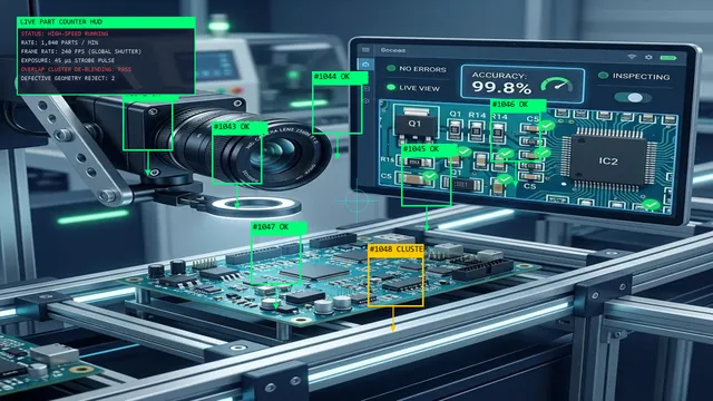
High-Throughput Vision Acquisition Pipeline Specifications
| Pipeline Stage | Execution Mechanism | Throughput SLA |
|---|---|---|
| Frame Ingestion | Zero-Copy DMA via GigE Vision / CoaXPress | 240 FPS stream with < 0.5 ms acquisition jitter. |
| CUDA Pre-Processing | Hardware Bayer Demosaic + Letterbox Scaling | 1.1 ms execution latency on onboard GPU memory. |
| INT8 TensorRT Inference | Lightweight YOLOv10-N / ByteTrack Kernel | 2.4 ms per batch; resolves touching/overlapping parts. |
| Fieldbus Actuation | Opto-Isolated Digital Output / Profinet | Microsecond pneumatic reject blast actuation on defective geometry. |
1. High-Efficiency Neural Detection: TensorRT INT8 Quantization
High-resolution models designed for stationary scenes cannot sustain the 250 to 500 FPS throughput required for high-speed tracking. Instead, architectures utilize compact convolutional object detection networks (such as modified YOLOv8-nano or RT-DETR backbones) trained specifically on the target part family. These networks are post-training quantized (PTQ) from 32-bit floating-point precision (FP32) to 8-bit integer (INT8) representation using calibration datasets that capture diverse illumination fluctuations and product orientations.
Quantization to INT8 reduces memory bandwidth bottlenecks, allowing the model to fit entirely within the fast L2 cache of the GPU or embedded Tensor Processing Core. Running on an industrial embedded compute module such as the NVIDIA Jetson AGX Orin or an industrial PC equipped with an NVIDIA RTX A4000 GPU, the detection forward pass completes in just 1.4 to 1.8 milliseconds per frame.
2. Multi-Object Tracking with Kalman Filtering (ByteTrack)
Detection alone is insufficient for counting: when 40 parts fall through the frame simultaneously across consecutive frames, the system must assign unique, persistent tracking IDs (Trackk) to each physical unit to prevent duplicate tallies. Standard Euclidean distance matching fails when objects tumble or decelerate unevenly.
Our implementation employs an optimized linear Kalman filter integrated into a modified ByteTrack architecture. For every active track, the Kalman state vector models 2D spatial position, bounding box aspect ratio, scale, and their respective first-order temporal derivatives:
State Vector: x = [x, y, scale, ratio, vx, vy, vscale]T
During each frame interval t, the Kalman filter predicts the a priori state estimate of each tracked item based on its established velocity vector. The tracking engine computes an association cost matrix using Generalized Intersection over Union (GIoU) combined with cosine distance of visual feature embeddings. The Hungarian algorithm computes optimal bipartite matching between predicted tracks and detected candidate bounding boxes.
Crucially, ByteTrack preserves second-tier low-confidence detections rather than discarding them. If a pill or cap is momentarily occluded by dust, shadow, or another overlapping part, its detection score drops from 0.92 to 0.45. While standard trackers drop the track and initiate a new ID upon reappearance (causing double counts), ByteTrack matches the low-confidence box with the predicted Kalman trajectory, maintaining ID continuity and eliminating duplicate count increments.
3. Overlap and Shingling Resolution: Morphological Splitting
When items pass down the chute touching edge-to-edge, the neural detector may output a single combined bounding box encompassing both units. To resolve this edge case, our vision pipeline implements a secondary stage CUDA-accelerated morphological separation layer:
- Extract the binary segmentation mask of the candidate cluster.
- Compute the Euclidean Distance Transform (EDT) across the foreground pixel array.
- Identify local maxima representing distinct physical mass centers within the cluster.
- Execute a marker-controlled watershed transformation to segment the touching boundary along the saddle points of minimal pixel thickness.
- Instantiate two separate tracker nodes with independent trajectory vectors, guaranteeing both items are accurately registered as they traverse the count boundary.
PLC Integration and Real-Time Diverter Actuation
Accurate counts are useless if they cannot be synchronized with packaging automation equipment in real time. Discrete packaging lines utilize Programmable Logic Controllers (PLCs) to orchestrate downstream bagging, box cartoning, blister sealing, and reject diverters. When a designated batch count is attained (e.g., exactly 100 capsules per bottle), the vision system must notify the PLC to index the rotary carousel with zero delay.
Our edge AI architecture provides dual-path communication to industrial automation systems:
- Direct Hardware GPIO Optocoupler Output: For ultra-low latency applications requiring microsecond responsiveness, the edge IPC features isolated 24V industrial digital outputs. When a verified part traverses the virtual count boundary, a hardware timer triggers a 24V square-wave pulse with a duration of 500 microseconds and an electrical rise time under 15 microseconds, directly feeding the high-speed counter card of the PLC.
- Deterministic Industrial Fieldbus (PROFINET / EtherNet/IP / Modbus TCP): In parallel with discrete trigger pulses, the edge vision system operates as an Industrial Ethernet slave node. At cyclic update intervals of 2 milliseconds, the vision processor writes process data arrays containing total gross count, net qualified count, defect count, instantaneous throughput rate (parts/second), and track health diagnostics into the PLC input register memory blocks.
Failsafe Engineering and Error Handling
Deploying mission-critical AI vision onto 24/7 manufacturing floors requires defensive engineering architectures designed to withstand mechanical and optical edge cases:
- Optical Lens Contamination Monitoring: The software continuously tracks background pixel variance and high-frequency edge gradients across non-part reference zones. If sugar dust, oil, or particulate buildup attenuates edge sharpness below calibrated contrast thresholds, the system flags an automated pre-warning alarm to the SCADA system, scheduling maintenance before counting accuracy degrades.
- Watchdog Heartbeat Interlocks: A hardware watchdog relay connects the edge vision computer to the line emergency-stop and diversion loop. If an unhandled thread exception, GPU thermal throttling, or OS freeze delays the cyclic heartbeat signal by more than 10 milliseconds, the relay opens, instantly commanding the PLC to divert uninspected parts into a quality quarantine bin.
- Full Frame Audit Buffering: When the vision system flags an anomalous condition—such as an unclassifiable object cluster, a sudden velocity surge exceeding physical conveyor limits, or a chipped part—the raw uncompressed frames are buffered in high-speed NVMe storage. Plant engineers can review frame-by-frame replays, inspect bounding box coordinate logs, and retrain models to continuously improve line resilience.
To evaluate the direct financial impact of switching from sensor-based counting to high-speed AI vision, utilize our interactive Computer Vision ROI Estimator. You can also explore our end-to-end integration workflows on our dedicated manufacturing AI solutions page, or contact our engineering team to design a customized high-speed inspection cell for your production facility.
Frequently Asked Questions
Why do through-beam photoelectric sensors fail when counting small parts at high speeds?
Photoelectric sensors measure binary optical beam interruption. When parts travel at high speed, they frequently tumble, bounce, or overlap (shingling). Touching parts create a continuous optical occlusion, registering as a single part. Conversely, tumbling or fluttering parts can break the beam multiple times, causing false double-counting. Physical sensors also suffer from dust deposition and lens contamination on 24/7 lines.
How does computer vision track items when they touch or overlap on a conveyor chute?
Edge AI vision systems combine deep learning object detection with morphological post-processing. A convolutional neural network identifies the general shape contours, while Euclidean distance transform and marker-controlled watershed algorithms locate independent mass centers and split touching boundaries. Multi-object tracking algorithms like ByteTrack maintain persistent trajectory vectors across sequential frames, ensuring each unit is counted individually.
What camera shutter and lighting specifications are required to count at 200+ parts per second?
The system requires an industrial global shutter CMOS camera operating at 250 to 1,000 frames per second over GigE Vision or CoaXPress interfaces. To eliminate motion blur without compromising image contrast, microsecond-pulsed LED strobe lights provide high-intensity illumination for 2 to 5 microseconds per exposure, freezing parts traveling at up to 15 meters per second with sub-pixel sharpness.
What is the latency between visual detection and PLC trigger actuation?
On optimized edge hardware such as the NVIDIA Jetson AGX Orin, total pipeline latency from sensor photon exposure through TensorRT INT8 neural inference, tracking association, and digital GPIO output transmission is deterministically maintained between 2.8 and 4.0 milliseconds. This leaves ample time for PLC-controlled diverters and packaging gates to actuate reliably.
Can the vision system detect broken, deformed, or foreign items while counting?
Yes. Unlike binary sensors that only count transitions, computer vision inspects the complete visual geometry, area, aspect ratio, and color profile of every part. If an item is chipped, undersized, or identified as foreign debris, the system simultaneously tallies the defect count and triggers an upstream pneumatic diverter to eject the defective part without interrupting the primary counting stream.