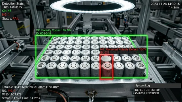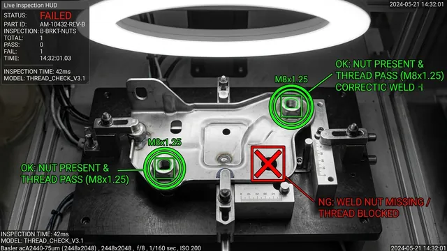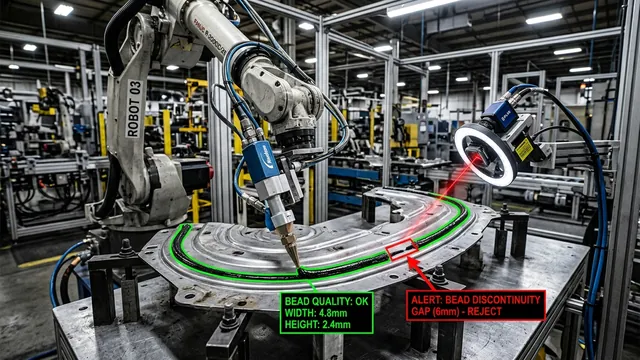

Direct Part Marking (DPM) is the gold standard for lifecycle traceability in automotive powertrain, aerospace turbine, medical device, and semiconductor manufacturing. Unlike paper labels or adhesive barcodes that degrade under extreme heat, chemical degreasers, or abrasive wear, DPM permanently embeds identification codes—such as 2D Data Matrix symbols, dot-matrix alphanumeric strings, and human-readable serial numbers—directly into the physical substrate of the component.
However, reading these permanent marks under real-world factory conditions is one of the most notoriously difficult challenges in industrial machine vision. Cast iron engine blocks exhibit granular surface roughness; machined aerospace alloys produce blinding specular glare; silicon wafers require microscopic SEMI font decoding; and automotive transmission shafts present extreme cylindrical curvature. When parts are coated in cutting fluids, residual oils, or shot-peened textures, traditional rule-based optical character recognition (OCR) algorithms fail completely.
Evaluating Automated Optical Inspection for Your Line?
Send us 5–10 sample images of your OK/NG parts or share your cycle-time and lighting constraints. Our Computer Vision architects will benchmark detection feasibility within 48 hours—or join a 20-minute technical scoping session.
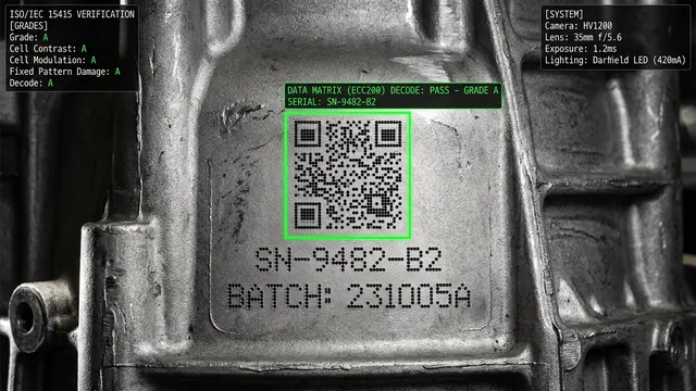
Key Takeaways
- The Failure of Classical OCR: Rule-based binarization (e.g., Otsu, Sauvola, Bradley thresholding) collapses when surface roughness ($R_a > 3.2\ \mu\text{m}$) or specular sheen exceeds stroke contrast, or when dot-peen markers produce disconnected impact craters rather than continuous character strokes.
- Deep Learning Architecture Shift: Modern industrial OCR deploys end-to-end neural pipelines combining differentiable binarization text detectors (DBNet), spatial transformer rectification networks (TPS-STN) for curved surfaces, and sequence decoders (CRNN with CTC loss or Vision Transformer TrOCR).
- Optical & Photometric Engineering: Achieving reliable character edge definition requires physics-based illumination: low-angle grazing darkfield lighting to highlight crater rims, diffuse integrating domes to kill convex glare, and cross-polarized filters to penetrate residual oil and coolant films.
- Strict Standards Compliance: Industrial verification must align with ISO/IEC TR 29158 (AIM DPM-1-2006) and ISO/IEC 15415, measuring metrics like Cell Contrast (CC), Cell Modulation (CM), and Axial Non-uniformity (ANU) directly at line speeds.
The Physics of Direct Part Marking and Surface Degradation
To engineer an automated reading system, one must understand how characters are formed on the material substrate and how subsequent manufacturing processes degrade optical legibility.
1. Common DPM Application Technologies
- Pneumatic Dot-Peen (Micro-Percussion): A carbide or diamond-tipped stylus repeatedly strikes the metal surface, creating conical or hemispherical indentations. The characters are not continuous lines; they are discrete clusters of crater depressions (typically in 5x7 or 7x9 matrices). The optical contrast is generated solely by shadow and directional reflection within the crater walls.
- Fiber Laser Ablation & Laser Annealing: High-energy laser pulses vaporize surface material (ablation) or induce localized thermal oxidation (annealing) to alter the metal's refractive index without altering surface topography. While annealed marks on stainless steel offer high initial contrast, subsequent heat treating or passivation baths can fade the mark into the surrounding metal tone.
- Cast-in-Mold & Forged Embossing: Raised or recessed characters formed directly during foundry casting (e.g., engine blocks, brake calipers, pump housings). These marks have identical color, metallurgy, and reflectivity to the parent part, differing only in surface height (relief).
- SEMI Font Laser Soft-Marking: Silicon wafers and lead frames feature microscopic alphanumeric strings governed by SEMI M12/M13 and SEMI T7 standards. The mark depth is often less than 2 microns, demanding specialized optical magnification and monochromatic illumination.
2. The Factory Floor Degradation Matrix
In assembly plants, marked parts undergo washing, machining, and chemical exposure. A serial number stamped on a raw aluminum die-casting must survive:
- Machining Coolants and Cutting Oils: Hydrocarbon films create undulating refractive puddles over characters, causing severe localized lensing, refractive distortion, and blinding mirror glare.
- Shot-Peening and Sandblasting: Surface hardening processes pit the parent metal, creating background noise that mimics the diameter and depth of dot-peen indentations.
- Thermal Scaling and Oxidation: Heat treatment creates variable iron-oxide scaling that flakes off unevenly, partially destroying character strokes.
- Physical Abrasion: Parts tumbling in conveyor chutes suffer scratches, gouges, and burrs that intersect and fragment alphanumeric characters.
Why Traditional Rule-Based OCR Fails on Industrial Metal
For decades, machine vision systems relied on classical morphology and intensity thresholding. The legacy pipeline followed a rigid sequence: grayscale conversion $\to$ background leveling $\to$ global/adaptive binarization $\to$ connected component analysis $\to$ character template matching.
This classical approach breaks down catastrophically in industrial DPM environments due to fundamental algorithmic assumptions:
Assumption 1: Bimodal Pixel Distribution
Classical binarization algorithms like Otsu's method assume the histogram of pixel intensities exhibits two distinct modes: dark foreground text and bright background substrate (or vice versa). On a cast iron gearbox housing, however, the surface texture produces a wide, continuous Gaussian histogram. Applying a global or local threshold either dissolves the characters into the background noise or fills the entire frame with binary speckle artifacts.
Assumption 2: Continuous Character Strokes
Morphological filters assume characters are made of continuous, closed contours. A dot-peen letter "B" or digit "8" consists of 12 to 18 disconnected micro-craters. To make standard OCR engines recognize dot-peen text, classical software attempts morphological dilation (smearing pixels) to fuse the dots. If the dilation kernel is too small, the characters remain disconnected and unrecognized; if the kernel is one pixel too large, adjacent characters merge into an illegible blob, or background machining chatter is erroneously joined into false characters.
Assumption 3: Planar Presentation
Template matching algorithms require characters to be planar and orthogonal to the camera axis. When a serial number is stamped along the radius of a 25 mm cylindrical camshaft or a curved aerospace turbine blade, characters near the outer edges undergo non-linear perspective compression and illumination drop-off, causing rigid template match scores to plummet below acceptable thresholds.
Replacing these fragile heuristics requires enterprise computer vision services designed around robust deep learning models that generalize across noisy, variable industrial environments.
Advanced Deep Learning OCR Architectures: DBNet, CRNN, and TrOCR
Modern industrial AI vision systems treat text recognition not as a fragile pixel-segmentation problem, but as a robust hierarchical sequence-modeling and attention task. The state-of-the-art industrial OCR pipeline comprises three decoupled deep learning stages:
The Modern 3-Stage Neural OCR Pipeline
Stage 1: Real-time differentiable text detection (DBNet) localizes arbitrarily oriented text lines.
Stage 2: Spatial Transformer Networks (TPS-STN) rectify curved or perspective-distorted surfaces into flat horizontal feature strips.
Stage 3: Sequence recognition via CRNN with CTC loss or Vision Transformer (TrOCR) decodes characters without requiring discrete single-letter segmentation.
1. Text Detection: Differentiable Binarization (DBNet)
Traditional text detectors use standard segmentation masks followed by non-differentiable binarization post-processing, which is computationally expensive and struggles with tightly clustered text. DBNet integrates the binarization step directly into the neural network training objective using a differentiable approximation of the step function:
$$\hat{B}_{i,j} = \frac{1}{1 + e^{-k(P_{i,j} - T_{i,j})}}$$
Where $P$ is the probability map, $T$ is the adaptive threshold map learned by the network, and $k$ is an amplification factor. By training the network to adaptively boost thresholds along character edges while depressing thresholds in noisy metal grain regions, DBNet accurately segments laser-etched and dot-peened text boxes even on severe background textures in less than 15 ms on edge hardware.
2. Geometric Rectification: Thin-Plate Spline Spatial Transformers (TPS-STN)
When marking cylindrical parts (tubes, pins, shafts), text follows a circular curve. Instead of complex mechanical rotation fixtures, the vision pipeline passes the detected text polygon through a Spatial Transformer Network (STN). The STN predicts a set of fiducial control points along the text baseline and computes a Thin-Plate Spline (TPS) transformation matrix.
The TPS operation mathematically unwraps and rectifies the curved, perspective-distorted metal surface into a normalized, flat, horizontal rectangular image patch. This eliminates geometric distortion before the image enters the recognition network, allowing a single neural recognizer to read both flat plates and high-curvature cylinders with identical precision.
3. Sequence Recognition: CRNN vs. Vision Transformer (TrOCR)
Once the text line is normalized, it is decoded into text strings using one of two cutting-edge architectures depending on hardware constraints:
- CRNN (Convolutional Recurrent Neural Network + CTC Loss):
CRNN combines a lightweight CNN backbone (such as MobileNetV4 or a customized ResNet) that extracts a sequence of visual feature vectors from left to right across the text strip. These feature vectors are fed into a Bidirectional Long Short-Term Memory (BiLSTM) network that models contextual transitions between characters. Finally, a Connectionist Temporal Classification (CTC) layer transcribes the sequence into text.
Because CRNN does not slice the image into isolated character boxes, it effortlessly reads disconnected dot-peen matrices. The network learns the spatial cadence of dots forming a letter without needing them to physically touch. A TensorRT-optimized CRNN engine executes in under 8 ms on an NVIDIA Jetson Orin Nano, making it ideal for high-speed conveyor lines.
- TrOCR (Transformer OCR with Visual-Language Attention):
For severely degraded aerospace or nuclear traceability where characters are partially obliterated by gouges or thermal scale, Vision Transformers (TrOCR) provide superior accuracy. TrOCR uses a vision encoder (DeiT / ViT) paired with a causal autoregressive language decoder (BERT / RoBERTa).
The self-attention mechanism enables the model to infer missing or obscured characters through grammatical and contextual priors. If an oily smudge obscures the bottom half of an "E", but the internal part serialization format dictates an alphanumeric prefix "ENG-", the transformer resolves the ambiguity with 99.98% confidence, preventing unnecessary part rejections.
Synthetic Data Generation and Domain Randomization
Training deep neural networks on industrial DPM requires thousands of diverse images. Collecting real defect samples from live production lines is slow and expensive. At AdaptNXT, we train our OCR models using photorealistic synthetic data generation pipelines built in 3D physics engines (Blender and NVIDIA Omniverse).
We apply domain randomization: varying surface roughness ($R_a$), simulating carbide stylus wear (shifting dot craters from sharp cones to shallow flat indentations), altering laser power degradation, and applying procedural shaders representing coolant droplet streaks, rust pits, and machine scratches. Models trained on synthetic data achieve immediate out-of-the-box accuracy on real factory floors without requiring months of manual image labeling.
Optical Engineering: Dome, Darkfield, and Polarized Illumination
In machine vision, software algorithms process photons; if the optical setup fails to capture contrast, even a 100-billion-parameter model will falter. Direct Part Marking requires specialized lighting geometries tailored to surface topography.
| DPM Type & Substrate | Primary Optical Challenge | Optimal Illumination Geometry | Recommended Wavelength / Filtration |
|---|---|---|---|
| Pneumatic Dot-Peen on Machined Steel | Disconnected craters, shiny background machining marks | Low-Angle Darkfield Ring Light (< 15° incident angle) | Red (630 nm) or Blue (470 nm) with bandpass filter |
| Laser Annealing on Curved Stainless Tubes | Specular mirror reflection along cylinder axis | Diffuse Dome Light (Integrating Sphere principle) | White diffuse LED with continuous uniform dome baffle |
| Cast Iron / Sand-Cast Embossed Characters | Zero color contrast, heavy granular surface pitting | Directional Low-Angle Linear Glazing / Line Projector | Monochromatic Blue (450 nm) to cast deep relief shadows |
| Oily / Coolant-Soaked Automotive Gears | Hydrocarbon film causing severe specular glare and lensing | Cross-Polarized Coaxial or Multi-Angle Bar Lights | Linear polarizing film on light + 90° analyzer on lens |
| Silicon Wafer SEMI OCR (M12/M13) | Microscopic mark depth (< 2 $\mu\text{m}$), specular mirror silicon | Brightfield Coaxial Telecentric with High Magnification | Near-Infrared (850 nm) or Green (525 nm) monochromatic |
Darkfield Illumination Mechanics
Darkfield lighting is indispensable for dot-peen and engraved markings. In a darkfield configuration, light strikes the metallic surface at an extremely low grazing angle (typically 10° to 15° relative to the part plane). On a smooth metal surface, the light reflects specularly away from the camera lens according to Snell's Law ($R_{angle} = I_{angle}$), causing the flat background to appear deep black.
When the grazing light encounters the conical walls of a dot-peen crater or laser-etched trench, the micro-facets scatter light upward into the camera lens. The result is an image with inverted, crisp contrast: brilliant white crater rims standing out against an ink-black background, completely negating background surface color variations.
Cross-Polarization for Oil and Coolant Suppression
When parts exit CNC milling centers, they are coated in water-soluble coolant and synthetic cutting oil. Liquid droplets create unpredictable specular highlights that blind cameras. Standard diffuse lights cannot eliminate these liquid reflections.
Cross-polarization exploits the physics of light scattering. A linear polarizing filter is placed in front of the LED light source, emitting linearly polarized light waves vibrating in a single plane. When this light reflects off the shiny surface of an oil droplet (specular reflection), its polarization orientation is preserved. However, when light penetrates into the metallic microstructure and reflects diffusely, its polarization is randomized (depolarized).
By placing a second polarizing filter (the analyzer) in front of the camera lens and orienting it at 90 degrees to the light source polarizer, all specular reflections from the oil surface are completely extinguished (blocked by the analyzer). Only the depolarized light from the actual metal surface reaches the camera sensor, providing a pristine, oil-free view of the engraved code.
Traceability Standards: ISO/IEC 15415 and AIM DPM Compliance
In aerospace (ATA Spec 2000), medical implants (FDA UDI), and automotive safety components (AIAG B-17), industrial vision systems must do more than simply decode a string—they must grade mark quality to ensure the code remains readable throughout the component's 20-year service life.
Standard barcode verifiers rely on ISO/IEC 15415, which was designed for high-contrast black ink printed on white paper labels. When applied to direct part marks on metal, ISO/IEC 15415 invariably assigns a failing grade "F" due to low baseline reflectance and textured backgrounds. To resolve this, the international vision committee established ISO/IEC TR 29158 (AIM DPM-1-2006).
AIM DPM-1-2006 Quality Parameters
Our edge AI inspection systems evaluate codes against the continuous metrics defined by AIM DPM:
- Cell Contrast (CC): Measures the difference in reflectance between light and dark cells, utilizing continuous thresholding tailored to metallic substrates.
- Cell Modulation (CM): Analyzes the interior uniformity of each individual data cell. High modulation ensures that surface scratches within a single dot do not cause the decoder to flip bit values.
- Minimum Reflectance ($R_{min}$): Verifies that the darker elements of the mark absorb sufficient light relative to the nominal surface.
- Fixed Pattern Damage (FPD): Grades the integrity of the L-shaped "finder pattern" and alternating "clocking pattern" in a 2D Data Matrix code. If physical tooling damage clips the corner of the finder pattern, the FPD metric flags tooling wear before catastrophic decode failure occurs.
- Axial Non-uniformity (ANU) & Grid Non-uniformity (GNU): Quantifies aspect ratio elongation and shear distortion caused by improper part velocity on conveyors or miscalibrated laser galvo mirrors.
By monitoring these AIM DPM metrics in real time, our manufacturing AI solutions provide predictive maintenance alerts: if Cell Modulation begins trending downward across consecutive engine blocks, the system alerts maintenance that the dot-peen carbide pin is dulling or the laser optical protective window is clouded with soot.
Edge Hardware Architecture and MES Integration
Deploying deep learning OCR on high-speed industrial lines requires an edge architecture that combines real-time image acquisition with deterministic industrial fieldbus handshakes.
High-Speed GigE Vision Ingestion
We deploy industrial GigE Vision or USB3 Vision cameras (e.g., Basler ace 2, FLIR Blackfly S, or Lucid Vision Helios) utilizing Sony Pregius global shutter CMOS sensors (ranging from 2.3 MP to 12.3 MP). Global shutters are critical: rolling shutter sensors introduce severe geometric skew when parts move along high-speed conveyors at velocities exceeding 1.5 m/s.
The image stream is captured via hardware-accelerated GenICam pipelines into an industrial edge controller powered by the NVIDIA Jetson Orin platform or an industrial fanless PC with an NVIDIA RTX A4000 GPU. Using our optimized edge AI development framework, the raw Bayer pattern data is debayered directly in GPU memory using CUDA streams, bypassing host CPU RAM bottlenecks.
Deterministic PLC Handshake and Traceability Database Sync
When the optical sensor triggers, the inspection cycle executes deterministically:
- Opto-Isolated Hardware Trigger: Part presence laser sensor trips the camera opto-isolated trigger input; exposure begins within 15 microseconds.
- Preprocessing & TensorRT Inference: Image is rectified via TPS-STN; DBNet detects code bounds; CRNN or TrOCR decodes the serial string; execution takes 18 to 35 ms in FP16 precision.
- Fuzzy Logic & Checksum Validation: The decoded string is validated against an active MES batch sequence using Levenshtein distance matching and Luhn/CRC check algorithms to eliminate substitution errors.
- Industrial Fieldbus Dispatch: The result is transmitted via Siemens PROFINET, Rockwell EtherNet/IP, or OPC UA to the line PLC. If the grade drops below the ISO threshold or a character is unreadable, the PLC fires a pneumatic reject divert gate within 50 ms.
- Archival Telemetry: Every decoded image, along with its calculated AIM DPM grading scores and timestamped metadata, is pushed to an on-premise MinIO / S3 object store for ISO 9001 audit compliance.
Building Resilient Traceability for Industry 4.0
Direct Part Marking is the backbone of modern automotive, medical, and aerospace manufacturing. As regulatory mandates demand cradle-to-grave traceability for EV battery cells, surgical instruments, and aerospace turbine components, relying on fragile rule-based vision sensors is a recipe for line stoppages and warranty penalties.
By combining tailored optical physics—such as low-angle darkfield, diffuse dome, and cross-polarized filtration—with modern deep learning sequence models like DBNet, CRNN, and TrOCR, manufacturers can achieve near-100% first-pass read rates on the most challenging industrial surfaces. If your plant is struggling with unreadable laser marks, dot-peened serial numbers, or strict ISO grading audits, reach out to our machine vision engineers to schedule a feasibility evaluation on your physical parts.
Frequently Asked Questions (FAQ)
Why does classical thresholding fail to read dot-peen markings?
Dot-peen characters are composed of individual, disconnected micro-impact craters rather than continuous strokes. Classical thresholding (such as Otsu or Sauvola) relies on connected component analysis. It either fails to group the dots into characters or, when aggressive morphological dilation is applied, merges adjacent characters and background machining noise into an unrecognizable binary blob.
How does cross-polarization eliminate glare from oily metal parts?
When linearly polarized light strikes an oily or wet film, the specular reflection retains its polarization plane. In contrast, light scattering off the underlying metal substrate is depolarized. By placing an analyzer filter on the camera lens rotated 90 degrees to the illumination polarizer, the glare from the oil is blocked, allowing only the diffuse reflections from the metal characters to enter the camera sensor.
What is the difference between ISO/IEC 15415 and ISO/IEC TR 29158 (AIM DPM)?
ISO/IEC 15415 is designed for high-contrast printed labels (ink on paper) and invariably fails on metallic parts due to low baseline reflectivity and natural material texture. ISO/IEC TR 29158 (AIM DPM) was specifically developed for direct part markings on metallic, plastic, and reflective substrates, introducing optimized global thresholding, multi-angle illumination grading, and cell modulation metrics tailored to physical indentations.
Can deep learning OCR run fast enough for high-speed manufacturing lines?
Yes. When optimized using NVIDIA TensorRT in FP16 or INT8 precision on edge hardware like the NVIDIA Jetson Orin Nano or Orin NX, modern text detection and recognition pipelines (such as DBNet + CRNN) execute in 18 to 35 milliseconds per image. This comfortably supports line speeds exceeding 60 to 120 parts per minute.