
Modern automotive, aerospace, and high-density electronics manufacturing relies on complex wiring harnesses that distribute electrical power, high-voltage battery management signals, and mission-critical controller area network (CAN bus / automotive Ethernet) communications. In an electric vehicle (EV), a wiring harness can contain over 4,000 individual conductors, hundreds of multi-cavity connectors, and exceed 45 kilograms in total mass. Despite massive automation in cable cutting and terminal crimping, final pin insertion and connector assembly remain heavily reliant on manual labor.
A single misplaced pin, an unseated terminal that backs out under road vibration, or an inverted color sequence can cause catastrophic system failures—from disabled Advanced Driver Assistance Systems (ADAS) to intermittent battery management disconnections or automotive fires. Traditional tactile click checks and electrical continuity fixtures cannot detect mechanical defects such as partially latched Terminal Position Assurance (TPA) clips, slightly bent pin headers, or color sequence swaps that pass electrical testing due to unintended harness cross-bridging.
Evaluating Automated Optical Inspection for Your Line?
Send us 5–10 sample images of your OK/NG parts or share your cycle-time and lighting constraints. Our Computer Vision architects will benchmark detection feasibility within 48 hours—or join a 20-minute technical scoping session.
Key Takeaways
- Zero-Defect Mandates: Automotive Tier-1 suppliers and aerospace manufacturers operate under IATF 16949 and IPC/WHMA-A-620 Class 3 standards, where undetected harness flaws lead to immediate vehicle recalls and severe warranty liabilities.
- Dual-Vector Failure Modes: Automated inspection must simultaneously solve two distinct computer vision challenges: multi-conductor color sequence (pinout) verification across striped/extruded wires and sub-millimeter geometric metrology for bent, recessed, or unseated terminal pins.
- Optical Elimination of Glare: High-specular reflection off gold-, nickel-, and tin-plated terminals blinds standard ring lights. Diffuse on-axis coaxial lighting paired with bilateral telecentric lenses is mandatory to capture crisp, shadow-free cavity depths.
- Sub-150ms Edge Inference: Deploying optimized TensorRT deep learning models directly on factory-floor hardware (such as the NVIDIA Jetson Orin platform) provides immediate visual go/no-go feedback to operators without slowing tactile assembly cadence.
The Engineering Challenges of Wire Harness Assembly Inspection
Wire harness assembly lines are fast-paced, high-mix manufacturing environments. Operators manually seat precrimped wires into plastic connector housings (molded from glass-filled PBT or PA66 nylon). While operators are trained to listen and feel for the mechanical "click" of the terminal locking tang, tactile feedback is notoriously unreliable. Ergonomic fatigue, repetitive motion numbness, and ambient factory noise routinely result in partial insertions where the terminal tang rests on the housing shoulder without fully engaging the locking barb.
Automated visual quality control at these assembly stations must overcome several severe optical and physical hurdles:
1. High-Density Multi-Conductor Color Variations
Wire jackets feature primary base colors combined with longitudinal or helical spiral tracer stripes (e.g., white with violet tracer, green with yellow stripe). Batch-to-batch extrusion variations, dye lot differences, dust, matte versus glossy PVC/Teflon insulation, and ambient factory lighting shifts render classical RGB thresholding or color lookup tables (LUTs) completely brittle. Slight rotation of the wire within the cavity can hide the tracer stripe from a single camera angle, producing false-positive color sequence rejections.
2. Sub-Millimeter Geometric Defect Modes
Terminal pins inside automotive connectors (e.g., TE Connectivity, Molex, Delphi/Aptiv) are tiny, often with pitch centers of 1.27 mm, 0.64 mm, or smaller. Acceptable pin depth variation is strictly bounded, frequently within an axial tolerance of ±0.2 mm to ±0.3 mm. Defect modes that must be detected within a single image capture include:
- Pushed-Out / Recessed Pins: Terminals where the locking tang failed to engage, causing the pin to sink back into the housing cavity when mated.
- Bent or Misaligned Pins: Pins deflected beyond allowable true position limits (typically an angular runout exceeding 1.0° to 1.5° or a radial deviation greater than 0.15 mm from nominal center).
- Inverted or Rotated Terminals: Asymmetric terminal blades inserted upside down, damaging mating receptacles during harness coupling.
- Unseated Secondary Locks (TPA/CPA): Connector Position Assurance (CPA) and Terminal Position Assurance (TPA) secondary lock clips left in a pre-lock or semi-engaged state.
3. Extreme Specular Reflection and Deep Cavities
Terminal pins are crafted from stamped copper alloys plated with gold, silver, tin, or nickel. These polished metallic surfaces act as miniature mirrors. Standard ring lights or directional spotlights generate intense specular highlights (hotspots) that completely saturate image pixels, blowing out the edges of the pins and casting deep, impenetrable shadows inside dark black or dark gray connector cavities.
Overcoming these challenges requires deploying sophisticated computer vision services that combine custom-engineered optical illumination with advanced deep learning neural architectures on the edge.
Optical Engineering: Telecentric Lenses and Diffuse Coaxial Illumination
In precision machine vision, algorithmic performance is fundamentally bounded by image acquisition quality. No neural network can reliably measure a pin seated 20 mm deep inside a connector housing if optical perspective distortion skews its perceived position or if specular glare destroys its contours.
The Optical Rule for Connector Cavities
Standard Entocentric lenses suffer from perspective distortion: objects farther from the lens appear smaller, and off-axis rays view the side walls of connector cavities rather than looking straight down the pin bore. For multi-cavity connectors, bilateral telecentric lenses are mathematically mandatory to maintain constant magnification across the entire depth of field.
Telecentric Lens Selection and Perspective Error Elimination
Standard fixed-focal-length lenses capture light in an angular cone (typically 30° to 60° field of view). When imaging a 40-pin connector, pins positioned near the periphery of the image are viewed at an oblique angle. This parallax causes the side of the pin shank to obscure the cavity floor, making it impossible to accurately measure pin height or cavity seating uniformity. Furthermore, if the connector vibrates or shifts along the optical axis by ±1 mm, standard lenses change the apparent distance between pin centers.
A bilateral telecentric lens accepts only chief rays that are parallel to the optical axis in both object and image space. This ensures:
- Zero Perspective Distortion: The camera peers straight down every single cavity simultaneously across the entire Field of View (FOV).
- Magnification Invariance: Even if the assembly fixture shifts vertically by several millimeters, the calculated millimeter-per-pixel ratio remains perfectly constant, eliminating false dimensional drift.
- Sub-Pixel Edge Sharpness: Telecentric optics minimize chromatic and spherical aberrations, allowing edge detection algorithms to achieve sub-pixel resolution down to 5–10 microns.
Diffuse Coaxial (On-Axis) Lighting
To eliminate blinding glare and illuminate deep housing cavities, vision engineers utilize diffuse coaxial illumination. In a coaxial light head, light from an internal high-intensity LED array passes through a beam splitter (a semi-transparent 50/50 pellicle mirror or prism) positioned at a 45-degree angle to the optical path.
The beam splitter reflects light downward along the exact same optical axis as the camera lens. The light strikes the flat tip of the terminal pin perpendicularly and reflects directly back through the beam splitter into the sensor. This transforms the flat end of every pin into an ultra-bright, high-contrast circular or rectangular feature against the dark, absorbing backdrop of the plastic connector cavity, completely neutralizing side-wall reflections and specular washout.
For inspecting the rear wire entry (color sequence verification), the setup switches to a multi-angle diffuse dome or darkfield quadrant LED ring light. The dome light bathes the curved, glossy PVC wire jackets in omnidirectional, shadowless light, revealing fine tracer stripes regardless of wire twisting.
The Deep Learning Edge Inference Architecture
While classical geometric pattern matching (e.g., normalized cross-correlation, edge gradients) can verify rigid, perfectly aligned pins under sterile conditions, it consistently fails on real-world assembly benches where wires twist, bend radii vary, and connectors exhibit mold flash. A production-ready inspection station combines specialized deep learning models tailored for discrete verification tasks.
Multi-Stage Neural Inspection Pipeline
Modern wiring inspection utilizes a hierarchical, multi-stage inference architecture deployed on an edge computer:
- Connector Localization and Pose Estimation: A lightweight object detection model (e.g., an optimized YOLOv10 or RT-DETR backbone) identifies the outer connector housing boundary and key reference datum points (such as mounting tabs or polarizing ribs). The image is digitally aligned and perspective-corrected using an affine homography matrix.
- Cavity Grid Segmentation & Cropping: With the connector oriented, the system segments the precise $(x, y)$ coordinate boundaries of each individual terminal cavity, creating isolated regions of interest (ROIs) for every pin position.
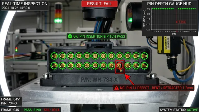
- Terminal Pin Metrology & Anomaly Detection: For each cavity ROI, a dedicated convolutional neural network combined with sub-pixel edge contour analysis determines:
- Pin centroid coordinate relative to nominal design CAD grid ($\Delta x, \Delta y$).
- Pin tip focus intensity or structured light triangulation profile to calculate depth ($\Delta z$).
- Binary classification: Seated, Unseated/Pushed-Out, or Bent.
- Color Sequence & Tracer Classification: For the rear wire entry view, an instance segmentation network (such as Mask R-CNN or YOLOv10-seg) segments each wire segment entering a cavity. The segmented patch is processed through a multi-label classification head that outputs the base insulation color, tracer stripe color, and stripe duty cycle, comparing the sequence against the bill of materials (BOM) wiring matrix.
Edge Computing vs. Cloud Latency
Tactile assembly workstations require immediate operator feedback. If an operator must wait 2 seconds for a cloud API call to verify pin insertion, productivity collapses, and operators will bypass the system. By deploying dedicated edge AI systems powered by embedded hardware like the NVIDIA Jetson Orin Nano (40 TOPS) or Jetson Orin NX (100 TOPS), inference executes locally in under 60 milliseconds.
Total station cycle time—including image capture, auto-exposure compensation, neural inference, pinout validation, and digital I/O signaling to an operator LED or pneumatic lock fixture—is completed in less than 120 milliseconds. This enables real-time guidance: the operator inserts a wire, and a green confirmation LED illuminates instantaneously.
Engineering Comparison: Manual vs. Legacy Vision vs. AdaptNXT Edge AI
Understanding the return on investment (ROI) and error-proofing capabilities requires evaluating the technical specifications across traditional and modern inspection paradigms:
| Inspection Metric | Manual Tactile / Visual | Traditional Machine Vision (Rule-Based) | AdaptNXT Edge AI + Telecentric Vision |
|---|---|---|---|
| Defect Escape Rate (PPM) | 1,500 – 3,000 PPM (Human fatigue) | 200 – 500 PPM (False alarms on wire twist) | < 5 PPM (Zero-defect target) |
| Inspection Cycle Time | 3.0 – 6.0 seconds per connector | 300 – 600 ms (Complex rule parsing) | < 120 ms (Optimized TensorRT FP16) |
| Color Stripe / Twist Robustness | Moderate (Subjective human perception) | Extremely Poor (Fails if stripe rotates out of ROI) | High (Semantic segmentation tracks helical twists) |
| Pin Depth Precision | Undetectable by eye (> 1.0 mm) | ±0.25 mm (Susceptible to glare) | ±0.05 mm (Coaxial telecentric metrology) |
| TPA / CPA Clip Verification | Physical push-pull check (Prone to omission) | Fixed threshold pixel counts | Keypoint spatial relation network |
| Recipe Changeover Time | Immediate (Requires retraining worker) | 4 – 8 hours (Manual tool reprogramming) | < 10 seconds (Barcode-driven CAD recipe load) |
Industrial Integration: Assembly Jigs, PLCs, and Error Handling
A machine vision inspection algorithm is only as good as its physical integration into the plant floor. In high-reliability automotive manufacturing, vision systems are embedded directly into assembly fixtures and smart assembly boards (jigs).
Tactile Assembly Jig Architecture
In our enterprise implementations at AdaptNXT, the inspection station features an integrated mechanical nest tailored to the specific connector body. The operator snaps the connector into the nest, which incorporates:
- Magnetic or Pneumatic Clamps: Locks the connector solidly in place against precision alignment pins, ensuring repeatable presentation to the camera.
- Dual Camera Configuration:
- Camera 1 (Mating Face View): Equipped with a 12MP Sony Pregius global shutter sensor, bilateral telecentric lens, and diffuse coaxial light to inspect terminal pin height, pitch, bend angles, and TPA engagement.
- Camera 2 (Wire Entry View): Equipped with a 5MP color global shutter sensor, wide-field telecentric lens, and a multi-angle diffuse dome light to inspect conductor insertion order and jacket strip length.
- Physical Interlocks: A pneumatic clamp prevents the operator from removing the connector until both cameras register a valid "PASS" signal. If a defect is detected, the fixture remains locked, sounding an audible alert and displaying an interactive touchscreen overlay highlighting the exact failing cavity and corrective action.
PLC Handshake and Traceability Integration
The edge vision controller interfaces directly with the station Programmable Logic Controller (PLC) via industrial fieldbus protocols, such as Modbus TCP, EtherNet/IP, or Siemens PROFINET. The handshake sequence follows a strict determinism:
- Part Present: Inductive proximity sensor detects connector insertion; PLC triggers edge camera capture line via opto-isolated 24V digital input.
- Vision Processing: Edge inference runs in < 80 ms; vision controller evaluates all pins and color sequences against the active CAD recipe.
- Result Output: The controller toggles discrete output lines (PASS / FAIL / REJECT_CODE) and writes a structured JSON telemetry packet containing pin depth coordinates, measured bend angles, and color sequence verification to the plant's Manufacturing Execution System (MES).
- Interlock Release: Upon receiving the PASS handshake, the PLC actuates the pneumatic clamp release and marks the serial number as valid in the database.
For more details on integrating visual AI with factory MES and PLCs, explore our dedicated manufacturing AI solutions.
Industrial Edge Cases and Fault-Tolerant Handling
Real-world production environments introduce edge cases that routinely disable naive vision systems. Robust engineering requires proactive software and hardware safeguards:
1. Ambient Light Fluctuations
Factory skylights, fluctuating fluorescent ballasts, and overhead crane shadows can alter image luminance. We implement shielded physical shroud enclosures around the optical nest paired with optical bandpass filters matched exactly to our LED illumination wavelength (e.g., 630 nm red or 470 nm blue). Ambient light is mechanically and optically attenuated by over 98%.
2. Twisted Wire Pairs and Color Misinterpretation
When multi-conductor cables are twisted for differential signal integrity (e.g., CAN high/low or Ethernet twisted pairs), the wire jacket twists sharply as it enters the connector grommet. If the tracer stripe rotates away from the primary camera axis, a standard 2D view can mistake it for a solid color. To resolve this, our edge architecture utilizes multi-view mirror prism arrays or an auxiliary angled camera, allowing the neural segmentation model to synthesize a complete 270-degree unwrapped perimeter representation of each wire jacket.
3. Mold Cavity Dimensional Tolerances
Plastic connector housings shrink and expand depending on resin humidity and mold cycle temperatures. A rigid pixel coordinate grid fails when housing dimensions shift by ±0.15 mm. Our pipeline uses dynamic datum referencing: rather than absolute pixel coordinates, pin positions are measured relative to the local molded cavity walls, ensuring that plastic shrinkage never triggers false pin runout errors.
Zero-Defect Quality Control for Next-Generation Electronics
As electric vehicles, autonomous driving systems, and aerospace avionics demand higher pin densities and smaller pitch tolerances, manual visual inspection is no longer economically or technically viable. Escaped wiring harness defects destroy brand reputation and result in multimillion-dollar recall campaigns.
By marrying precision bilateral telecentric optics, diffuse on-axis coaxial illumination, and optimized edge deep learning pipelines, manufacturers can achieve 100% automated inline verification with zero-defect escape rates at full production speeds. If you are designing automated assembly lines or retrofitting existing tactile workstations, contact our engineering team to discuss custom optical design, edge inference hardware, and turnkey machine vision integration.
Frequently Asked Questions (FAQ)
Why can't standard ring lights inspect terminal pins inside connectors?
Terminal pins are plated with highly reflective gold, tin, or nickel. Standard ring lights shine light at an angle, which causes intense specular hotspots on the pin shoulders and leaves the deep cavity floor shrouded in shadow. Diffuse coaxial (on-axis) lighting routes light along the exact optical axis of the camera, illuminating straight down the bore and reflecting cleanly back to the sensor without blinding glare.
How does telecentric optics eliminate perspective distortion in connector inspection?
Standard entocentric lenses capture angular rays, meaning pins positioned near the edges of a multi-pin connector are viewed from an angle, hiding the cavity floor and distorting their apparent distance. Bilateral telecentric lenses collect only parallel light rays across the entire field of view, maintaining constant magnification regardless of part distance and allowing direct orthogonal inspection of every pin simultaneously.
How do neural networks handle rotating tracer stripes on multi-conductor wires?
Unlike rigid rule-based systems that look for a stripe in a fixed pixel zone, modern deep learning architectures use semantic segmentation networks (such as YOLOv10-seg or Mask R-CNN) trained on thousands of wire orientation angles. The model identifies the entire contour of the wire jacket and detects tracer presence even when only a fraction of the helical stripe is exposed within the cavity entry.
What is the typical inference speed of an edge vision system on the assembly line?
On an industrial edge computer like the NVIDIA Jetson Orin Nano or Orin NX running TensorRT FP16 models, complete inference across 40+ cavities takes between 40 ms and 80 ms. Total workstation cycle time—including image acquisition, inference, and PLC digital I/O feedback—is completed well under 150 ms, providing instant feedback without interrupting operator takt time.